From a structural engineering perspective, walls are defined as vertical partitions within a building that may be load-bearing or non-load-bearing. They can therefore form part of a building’s primary or secondary structure. Walls are generally always BIM objects that define room boundaries. Depending on the specific software and objectives, different modeling strategies may be considered in the early planning phases—including, for example, multi-layer modeling.
This article describes general modeling guidelines for walls in the early stages and therefore concludes with the design phase. From this point on, the subsequent articles are organized by material or structural type.
In addition, there are special types of walls that are described in separate articles: mobile partitions and folding walls.
Search terms: walls, wall, slab, top edge, bottom edge, thickness, exterior, interior
In this phase, walls are modeled for the first time. It is not yet necessary to define materials (building materials).
Presentation
Plan view
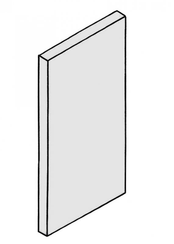
Model representation
Features
Feature
- Floor-to-ceiling element
- Floor-to-ceiling wall
- Status
- Load-bearing element
Parameters
- Gross floor area
- Gross floor area
- Gross volume
- Wall thickness
- Wall height
- Wall length
- Wall slope
- Net floor area
Outline Information
- Exterior element
- Room-enclosing element
Labeling
At this stage, the component is not yet labeled in the plan views.
Instructions
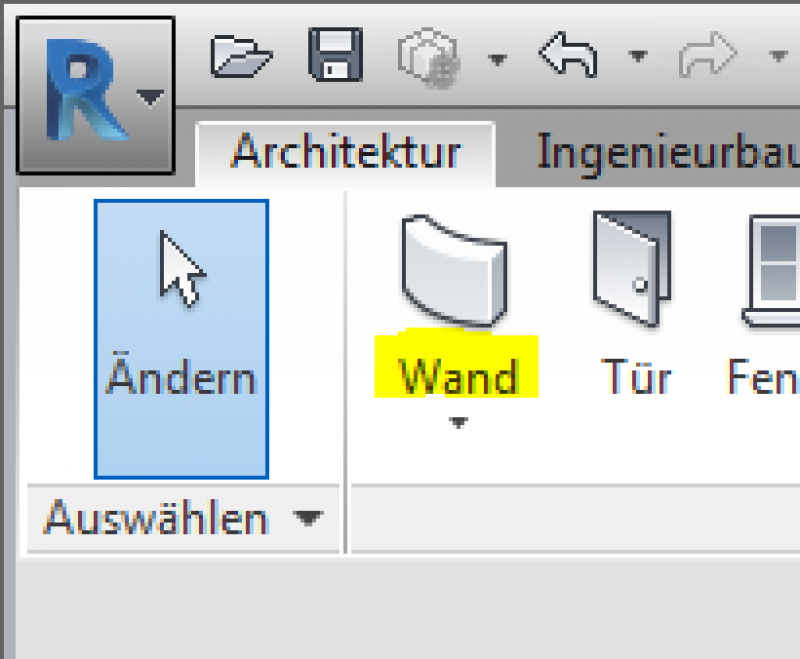
In Revit, walls are modeled using the Wall system family. As part of a building’s primary structure, walls are present in digital building models from the very beginning. Depending on the specific software and objectives, different modeling strategies may be considered in the early design phases (multi-layer, hybrid, and single-layer). Walls are modeled using the Wall tool in the Architecture tab.
Overview
The basic process of modeling a wall in ArchiCAD remains the same throughout the various design phases.
For ease of use in ArchiCAD, you can select the "Standard (single material)" setting.
For advanced users, it is recommended to always select the "Multi-layer" setting (or the "Complex Profile" for structurally more complex assemblies). The advantage of this is that even at the very beginning of a project, during the study phase when components are represented in a simple (single-color) display, the multi-layer structure allows for very precise control of the components right from the start. On the one hand, this defines specific, recurring structural thicknesses; on the other hand, a more precise definition of the structural element regarding its use is established right from the start.
Sharing the data with, for example, structural engineers allows for early communication of the intended structural design. Furthermore, this approach is highly recommended for saving time and optimizing a project: as soon as a structure catalog is available, these temporarily defined multi-layer components can be adapted to the structure catalog—construction elements that reference this multi-layer component immediately adopt this new structure.
For general information on how to use the Wall tool, please refer to the basic documentation provided by Graphisoft in the Help Center.
This documentation is based on the official template file 01 ARCHICAD 25 Template.tpl from the ARCHICAD 25 AUT version.
Building elements classified as walls essentially define the space and are categorized as load-bearing or non-load-bearing—they are thus defined as primary building elements or as Building Element Class I.
Note: Avoid using special settings (custom graphics, room surface effects) within the default wall settings in order to provide other/subsequent project collaborators with a clear structure that minimizes the risk of errors.
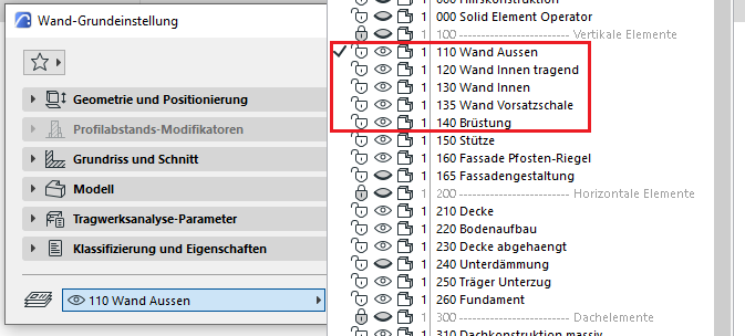
First, select the appropriate level for the specific wall application. These are categorized as follows: 110 Exterior Wall, 120 Load-Bearing Interior Wall, 130 Interior Wall, 135 Cladding Wall, 140 Parapet, and according to their structural design or specific application:
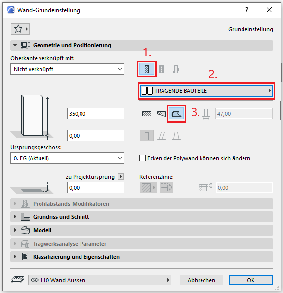
Geometry and Positioning
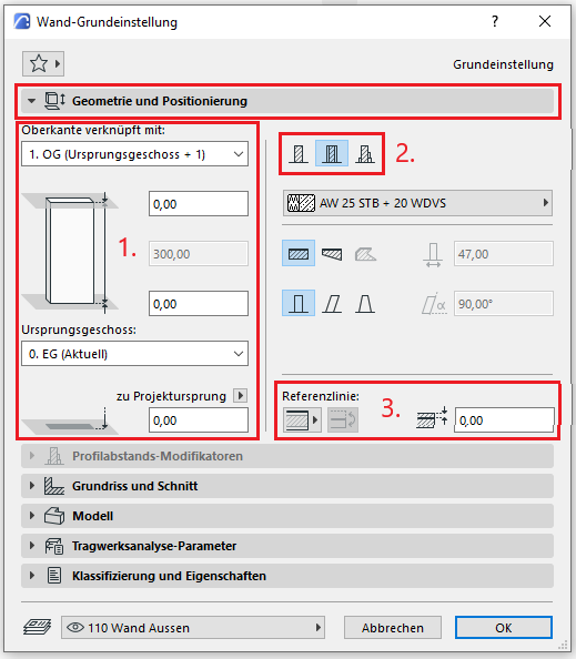
The first basic setting for geometry and positioning concerns the vertical dimension of the wall.
In accordance with ÖNORM A 6241-2, Annex A, a wall is always modeled on a floor-by-floor basis; in other words, it is not modeled across multiple floors. This is ensured if the setting “Wall top edge linked to:” is selected and a floor above the wall’s original floor is chosen as the floor link.
The second default setting defines the structure of a wall (and thus its thickness):
- Standard = (single) building material
- Multilayer = Multilayer component
- Complex profile
For basic use of ArchiCAD, you can select the "Standard (Single Material)" setting.
For advanced users, it is recommended to always select the "Multi-layer" setting (or the "Complex Profile" for structurally more complex assemblies). The rationale here is that even at the very beginning of a project, during the study phase when building elements are represented in a simple (single-color) display, the multi-layer structure allows for very precise control of the building element from the start. On the one hand, this defines specific, recurring wall thicknesses; on the other hand, a more precise definition of the wall regarding its use is established right from the start. A load-bearing exterior wall can thus be distinguished from a non-load-bearing shaft wall at a very early stage.
Furthermore, this approach is highly recommended for saving time and optimizing a project: as soon as a structure catalog is available, these temporarily defined multi-layer components can be adjusted accordingly—walls that reference this multi-layer component immediately adopt this new structure.
The third basic setting involves selecting the reference line of a wall. For load-bearing structural elements, this is the leading edge of the load-bearing material (e.g., reinforced concrete) or the core layer in a multi-layer component.
Manually offsetting the reference line by a certain amount is not recommended, as this adjustment is not automatically updated when the wall configuration (e.g., layer thickness) changes.
Profile Spacing Modifiers
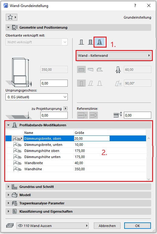
- If the wall has a complex profile and modifiers have been applied to it, the Profile Offset Modifiers tab is enabled
- The available modifiers and their values can be found in the tab.
Floor plan and cross-section
Model data can also be displayed using projections in floor plans, elevations, and sections—the following description explains the available options.
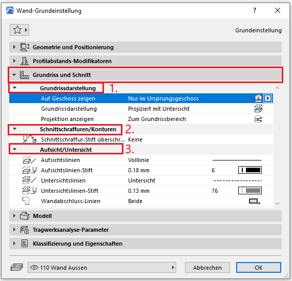
In the Floor Plan and Section section, the default setting for floor plan display is that walls are shown only on the base floor and projected with a bottom view. The projection should always be set to the floor plan area to allow for changes to the normal floor plan section plane in individual detail sets.
Section hatching and outlines should not be overridden in individual wall settings—these should always be configured centrally in the multi-layer part/material so that they apply to all components, or the "Graphical Override Styles" option should be used for special/temporary display changes.
The setting for the bottom view line is defined using the "Bottom View" line to ensure that all bottom views are displayed consistently.
Model
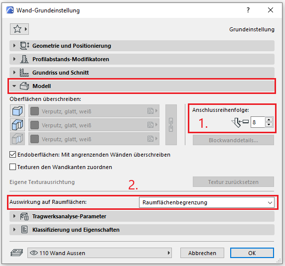
In the Model section, surfaces can be overridden manually or individually; however, to ensure a consistent representation, the Graphical Override Styles option should be used for special or temporary cases.
For walls that define a room, the "Room Area Boundary" option must always be enabled. If a different effect on room areas is selected, this must be noted (e.g., textual notes in the component ID)—this alerts the next project worker that there is a deviation from the standard room area calculation — this prevents errors in the area calculation.
Menu item: Structural analysis parameters
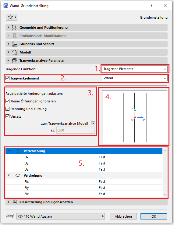
- You can specify whether the wall is load-bearing
- As an additional option, you can use the checkbox to specify whether the wall should function as a structural element or not. In the dropdown menu, you can select the type of structural analysis unit.
- The structural analysis unit differs from the physical model element. You can adjust the unit manually, or the automatic, rule-based changes will apply.
- You can manually change the position of the structural analysis unit in the preview window if the checkbox in step 3 is unchecked.
- You can enter the end constraints in this section.
Classification and Characteristics
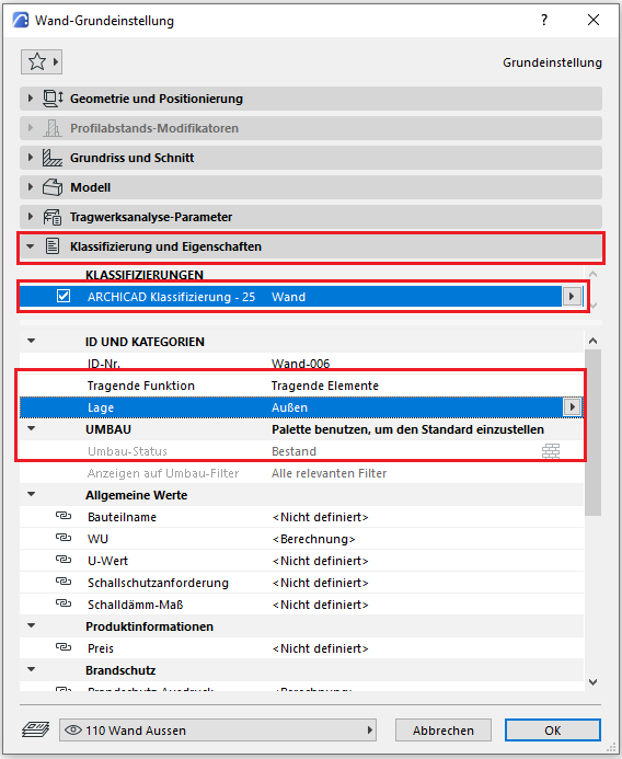
The element classification is the first definition in the Classification and Properties section—see also Classification. When you select a classification on the wall, only those properties are displayed in the lower field area that are available for that classification according to the IFC properties.
The three properties that also serve a specific function within ArchiCAD are Load-Bearing, Location, and Renovation Status—these affect either the structural representation method, the envelope function (in other programs), or the renovation filter. All other attributes must be selected individually or determined in accordance with the project’s organizational guidelines (e.g., project manual or organizational manual).
General Use
The process of modeling walls should always follow the same systematic approach—a description of this procedure can also be found in ÖNORM A 6241-2, Appendix A (Joints).
Specific Use
Example of Inventory Modeling
When modeling existing walls, it is recommended to use the "Polygon" geometry method:
- Method: Structure
- General building material for existing structures
- Geometric method: Polygonal
This method is effective for modeling warping and variations in wall thickness, which are common in existing buildings.
For more specific uses of building elements created with the "Wall" tool, see the following articles:
Wall: Construction and Wall Covering (Example: Cladding)
Presentation
Plan view
Model representation
Features
- Fire compartment-defining element
- Fire resistance class
Parameters
- Net display area
- Net volume
Outline Information
Labeling
At this stage, the component does not yet need to be labeled in the plan views.
Starting at this stage at the latest, walls are classified according to their material or construction type. The reason for this classification is that different workflows are used depending on the construction type, and therefore the graphical representations vary.
On BIMpedia, the use of the various wall families from this phase onward is therefore described in the following articles:
The template provided by BIM Office Administration includes basic wall types. Additional walls can be found in the associated family catalog.

Unfortunately, this content is available only to our Pro users.
If you'd like to read the full article, try the Pro account or become a Pro user.