At this stage, openings such as openings or slots are not yet represented as 3D objects. However, many BIM users employ openings at this stage to provide a simplified representation of doors and windows.
At this stage, openings, penetrations, and slots are not yet represented as specific 3D objects, but may simply be indicated on the floor plan using a surface scheme. The structurally relevant vertical and horizontal penetrations for the main routes of the building services (TGA) are specified using text.
The supplementary article "Construction Specifications and Planning for Slots and Openings" provides additional information on how to handle openings.
In this phase, cross-sections are first created using 3D objects designed specifically for this purpose and then supplemented with structural engineering and MEP data.
Presentation
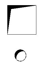
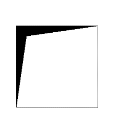
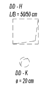
Floor breach
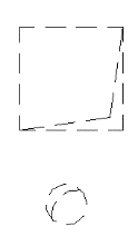
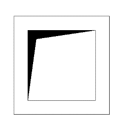
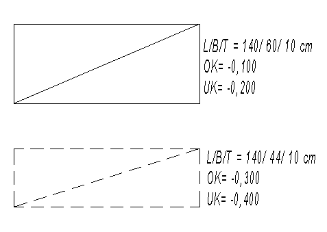
Ceiling breach
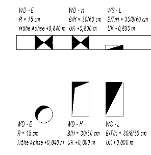
Wall opening
floor slot
img_19
img_19
img_23
Features
Labeling
At this stage, openings in plan views do not need to be labeled yet.
Instructions
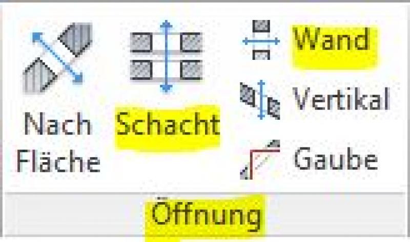
1) The required cutouts are created using the cutout functions:
Command: >Architecture >Opening command group >Shaft (in floor slabs), >Wall (in walls)
While these commands make it very easy to create an opening in a component, they do not provide the corresponding dynamic labeling or the floor plan symbols typically used for these components. For this reason, the second creation method is ultimately recommended:
2) Openings and slots are created using external (i.e., "loadable") families designed specifically for this purpose. These consist essentially only of cut-out bodies (hollow 'negative bodies') that cut out the necessary openings from corresponding base components such as floor slabs and walls. In such cases, these are referred to as so-called 'floor-based' or 'wall-based' components. Additionally, the corresponding floor plan symbols can also be incorporated into these families.
Since Revit does not provide a specific category for this purpose, openings are often assigned to the General Model category, which can be placed using the >Architecture >Element >Place Element command.
These families should be created using the family template files listed below:
- M_General Model (Floor Slab): for floor and ceiling openings
- M_General Model (Wall): for wall openings
For further instructions on using families of this type, see the Revit BOA Workflow.
In this phase, openings, cutouts, and slots are labeled in a way that is "approval-ready." This means that all openings must be replaced with cutout families.
Presentation
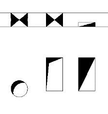
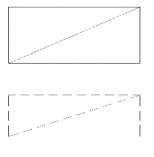
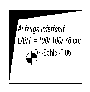
Elevator lobby
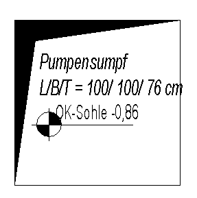
pump sump
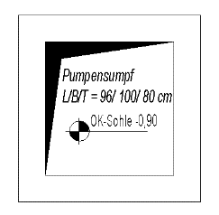
Pump sump with surround
img_38
img_40
img_42
img_44
Features
Labeling
When using the two primary methods for creating openings, cutouts, and slots, the following factors must be taken into account:
1) Revit does not provide any special labels for openings, cutouts, and slots created using the Revit opening tools.
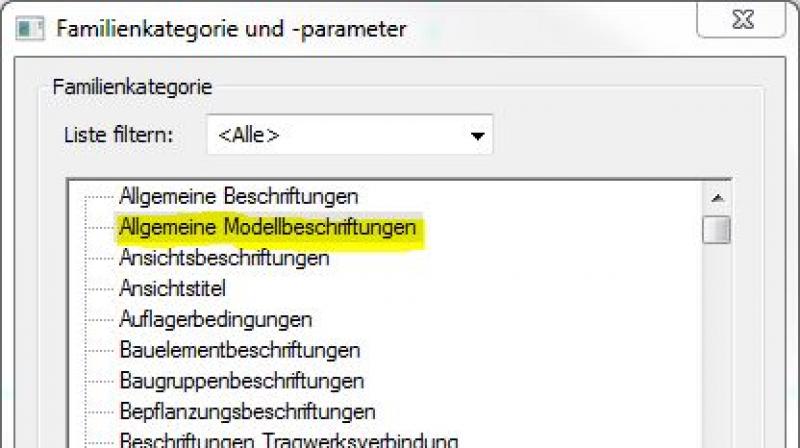
2) For labeling openings created using families in the General Model category, Revit uses General Model labels: Labels for General Models can be obtained from Revit Content. New labels can be created using the label family template >M_General Label (2) (= label for the General Model category):
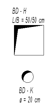
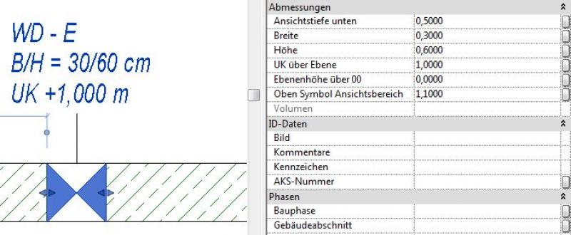
Ideally, the family is structured in such a way that the necessary information can be extracted from the parameters and properties of the structural components:
Objects for openings, niches, and slots are labeled in their object settings. In addition, the labeling and dimensioning scheme is always component-specific (adaptive).
The labeling and dimensioning of the component should always be done associatively. Instructions on how to do this in ARCHICAD can be found in the relevant articles.
Instructions
In this phase, the components are simply labeled. For information on creating the components, see the instructions in this article under >Design >Instructions.
At this stage, no further measures regarding openings, cutouts, or slots are taken (apart from any geometric adjustments required to accommodate building services and architectural needs).
Feature
- Reference
Parameters
Outline Information
Revit Content
The cutouts and empty openings created with the Window tool can also be managed centrally via the model view.

Unfortunately, this content is available only to our Pro users.
If you'd like to read the full article, try the Pro account or become a Pro user.