Internal insulation is used only in exceptional cases in building insulation. For building components where certain geometries or materials make it impossible to install the required external insulation, the use of internal insulation can reduce heat transfer. From a building physics perspective, interior insulation is a less effective solution compared to exterior insulation and should therefore only be used in exceptional cases.
No illustration of the interior insulation at this stage.
No illustration of the interior insulation at this stage.
The component is modeled for the first time during the design phase.
Presentation
Cross-sectional view
Model representation
Features
Feature
- Fire compartment-defining element
- Fire resistance class
- Sound insulation class
- U-value
Parameters
- Gross floor area
- Gross floor area
- Gross wall covering area
- Gross volume
- Thickness
- Height
- Length
- Slope
- Net floor area
- Net viewing area
- Net volume
Outline Information
- Room divider
Labeling
At this stage, the component does not need to be labeled yet
Instructions
Horizontal interior insulation is created using the floor slab system family. Vertical interior insulation is created using the wall system family.
- Interior insulation is generally non-load-bearing
- and are generally modeled as single-story structures
Create:
The methods for modeling interior insulation vary depending on the application as follows:
1. Horizontal interior insulation (floor slab)
The "Floor Slab" command is used to create thermal insulation along the load-bearing floor slab.
The appropriate reference level for ceiling insulation is the lower reference level of the load-bearing floor slab.
When insulating the ceiling, the room boundary should be enabled. To do this, check the corresponding box under "Dependencies" in the properties.

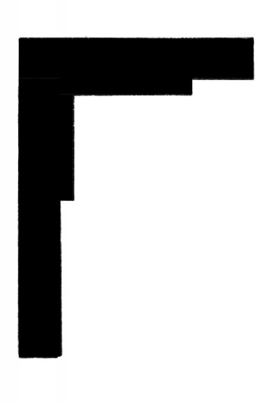
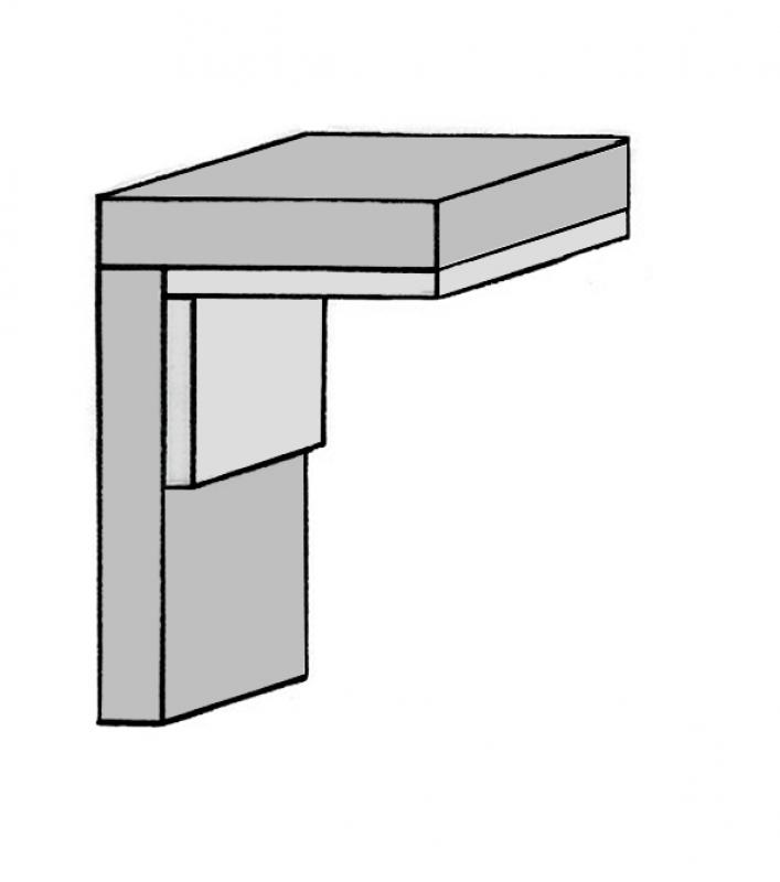
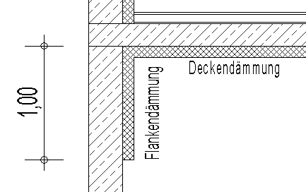
Ceiling insulation is extended all the way to the next wall. The top edge of the wall insulation is usually offset.
2. Vertical interior insulation (non-load-bearing wall)
The baseline of the interior insulation should always be on the same side as the wall being insulated. If the insulation thickness changes at a later stage, the insulation will not be manually repositioned in this case. Using the Wall -> Non-Load-Bearing Wall command, the thermal insulation is placed along a previously created load-bearing wall.
Full-height wall insulation
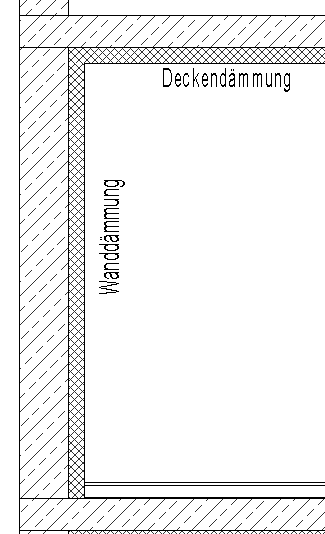
Floor-to-ceiling wall insulation should always be flush with the top edge of the rough ceiling. If the floor continues up the wall, it should be flush with the top edge of the floor.
3. Support insulation
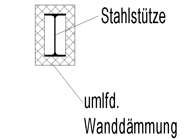
The room boundary should be enabled for column insulation.
4. Side insulation
Wall – Floor
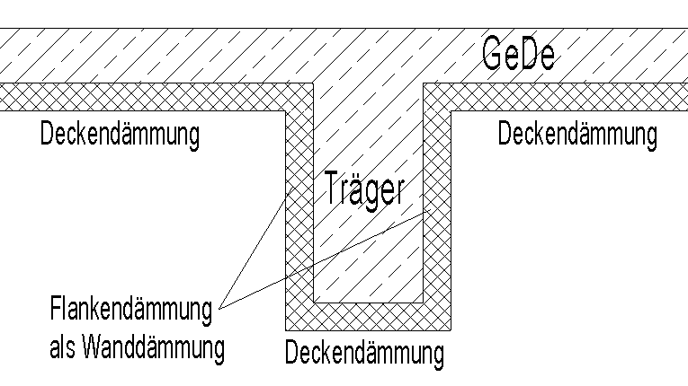
5. Beam insulation
Support â?? Floor slab
The basic process of modeling interior insulation (in addition to the general wall construction) using the Wall tool in ARCHICAD remains the same throughout the various design phases.
Detailed instructions on walls can be found under "Walls: General."
Interior insulation can be created as a complex profile, provided it does not cover the entire surface of the underlying structural element (ceiling or wall).
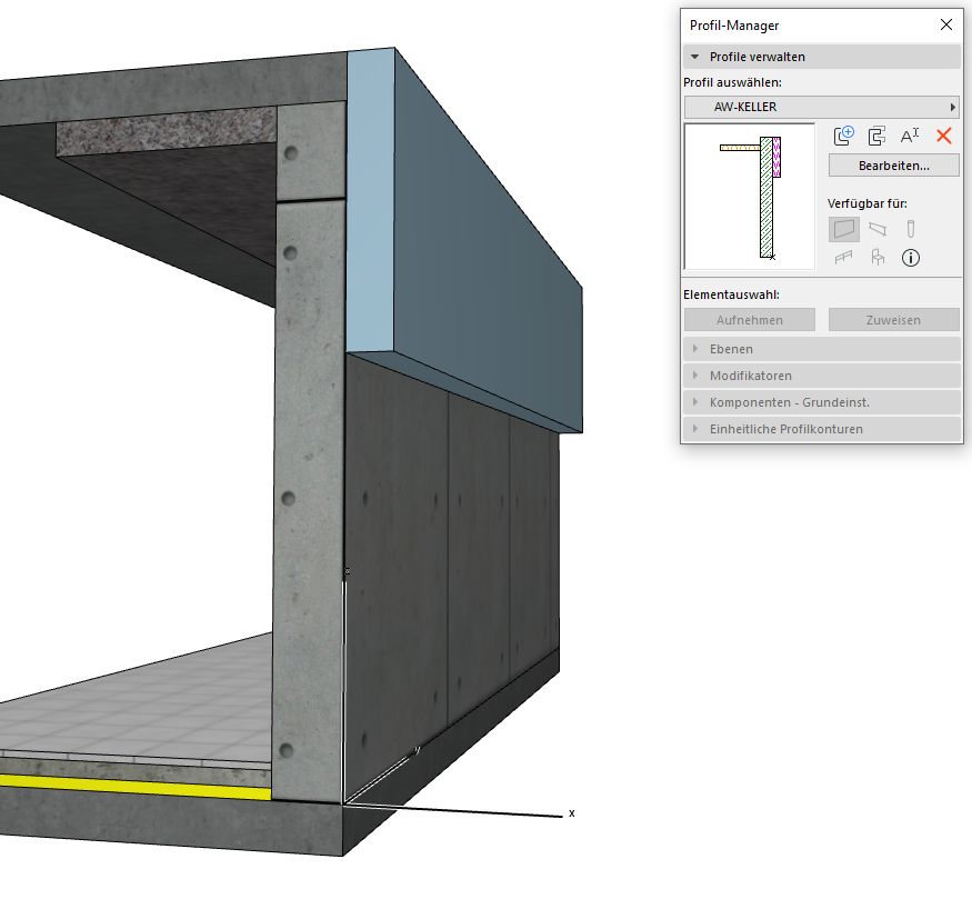
Example of a basement exterior wall with perimeter insulation:
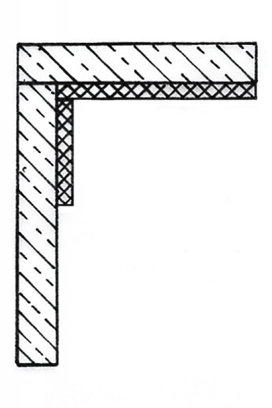
An exterior wall in the basement consists not only of multiple layers, but also of different types of side finishes—perimeter insulation on the sides (not covering the entire wall surface) and interior insulation on the sides against the ceiling above the basement. Therefore, modeling with a single multi-layer component is insufficient, and the "Complex Profile" structural method is used:
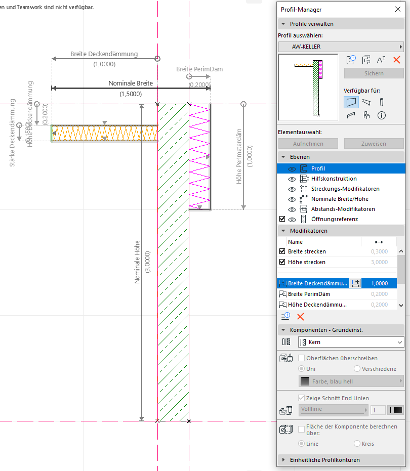
The availability is set to "Wall," since this type of exterior wall is also modeled using the Wall tool. When creating the profile, be sure to set a vertical extension range so that you can adjust the height of the modeled profile. You can create additional modifiers to edit the different insulation layers as needed in the 3D view. You only need to create one profile—no additional profile variants are required to achieve different material thicknesses—because the modifiers allow for real-time adjustments.
Presentation
Cross-sectional view
![Innendaemmung_Schnittdarstellung_solid_fill_farbig[1].jpg](/media/B55417CBF545F5AA0D826B97E9592611/innendaemmung_schnittdarstellung_solid_fill_farbig[1].jpg)
Features
Labeling
Due to the wide variety of regulatory requirements, there is no one-size-fits-all solution for this phase. However, here are some general guidelines for improving quality and preventing errors:
- For graphical customizations, you should always use view templates instead of making individual adjustments for each drawing.
- For additional information in the drawing content, always use text families instead of plain text.
- If a component catalog exists, this designation could be incorporated into the wall properties and read using a suitable label family.
The new features and parameters added for this phase must be entered in the appropriate fields of the component's settings dialog.
A description of the settings dialog and the corresponding procedure can be found in the article "Wall: General" or in an earlier section of this article.
The labeling and dimensioning of the component should always be done associatively. Instructions on how to do this in ARCHICAD can be found in the relevant articles.
Instructions
The attributes are assigned to the properties of the interior insulation so that this information can be reused in the context of BIM or, for example, retrieved via labels.
Depending on the characteristic, an appropriate label family should be used.
The new features and parameters added for this phase must be entered in the appropriate fields of the component's settings dialog.
A description of the settings dialog and the corresponding procedure can be found in the article "Wall: General" or in an earlier section of this article.
The labeling and dimensioning of the component should always be done associatively. Instructions on how to do this in ARCHICAD can be found in the relevant articles.
Presentation
March 30, 2017
March 30, 2017
Features
Feature
- Reference
Parameters
- Gross weight
- Net weight
- Net area of wall covering
- Thickness of wall covering
Outline Information
Labeling
If necessary, additional labels should be added to the plans to identify features.
Instructions
The attributes are assigned to the properties of the interior insulation so that this information can be reused in the context of BIM or, for example, retrieved via labels.
Depending on the characteristic, an appropriate label family should be used.
The new features and parameters added for this phase must be entered in the appropriate fields of the component's settings dialog.
A description of the settings dialog and the corresponding procedure can be found in the article "Wall: General" or in an earlier section of this article.
The labeling and dimensioning of the component should always be done associatively. Instructions on how to do this in ARCHICAD can be found in the relevant articles.
Openings in the structural wall (doors and windows) can be transferred to the interior insulation wall using the "Connect Geometry" command under "Modify."
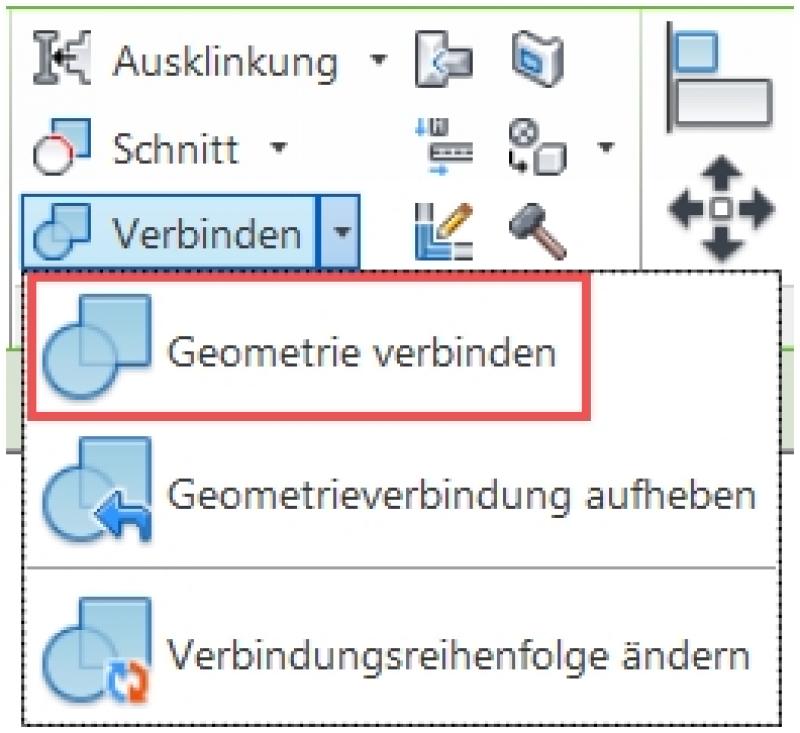
For more information on the topic of joining geometric patterns, see also the article on wall coverings
Horizontal structural elements, such as joists, can be cut out of wall insulation using the "Modify > Connect" command (click sequence: 1. Wall insulation, 2. Joist).
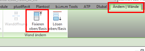
The top edge of walls can be snapped to the bottom edge of the ceiling insulation using Modify > Modify Wall > Snap to Top/Base. This ensures that the wall height is automatically adjusted whenever the thickness of the ceiling insulation is changed.
Ceiling underlayment does not have to be part of a complex profile; it can also be modeled as a standalone multi-layer component beneath the floor slab. The reference line for this ceiling underlayment should then be set to the internal top edge so that the underlayment can be extended downward or reduced in the event of a modification.

Unfortunately, this content is available only to our Pro users.
If you'd like to read the full article, try the Pro account or become a Pro user.