In this phase, only the structural components of the parapet are modeled. For more information, see the relevant articles: Wall: General, Wall: Masonry, Wall: Reinforced Concrete, and Beams and Girders (for steel structures). The parapet finishing components (substructures and coverings) are not yet modeled in this phase; however, they can alternatively be represented using a widened wall element that symbolizes the finished top edge of the component in place of the parapet structure.
In this phase, the substructures and coverings are created for the first time, in addition to the parapet shell components already created in earlier phases. Generally, for modeling reasons, it is recommended to model the individual parts of a parapet as a single combined component, since the finished parapet structure ultimately forms a single structural unit.
Presentation
Cut
Floor plan
Model representation
Features
This object is created during this phase. The required characteristics are generated through the modeling and material definition of the object.
The following characteristics are defined in this phase:
- General: TYPE (designation), type designation, BOA part code (type comment)
- Generating: Thickness, Length, Width, Height, Non-parallel Surfaces, Cross-sectional Area
- Calculated: Area, Perimeter, Volume, Lateral Surface Area
- Simulation: Location of the building element, floor
- Arch: Location of the building element, component reference, floor
- Material: Material, Material Grade
Labeling
At this stage, Attiken labels only the structural components in the floor plans. For more information, see the relevant articles listed in the "Conceptual Preliminary Planning" section.
Instructions
In general, there are three different ways to create parapets in Revit:
1) Wall profiling
2) Handrail
3) Project family / Sweep
The methods listed under points 2) and 3), including their advantages and disadvantages, are described in detail below. For point 1), instructions can be found in the Revit PRO section.
2) Version with railing:
Among other things, the >Railing command can also be used for parapets. With the advanced railing functions available starting with version R2017, it is now possible to place railings on wall top edges (both horizontal and sloped!) as well as on base components in the floor slab category!
The following steps are required to model a parapet as a railing:
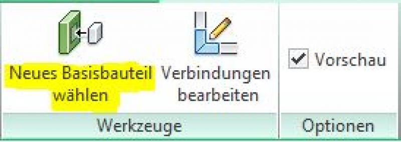
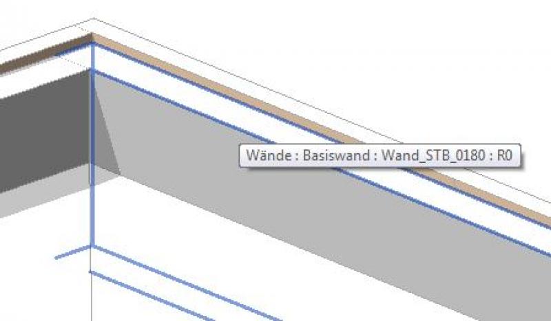
- Create a railing using the command >Railing >Sketch Path:
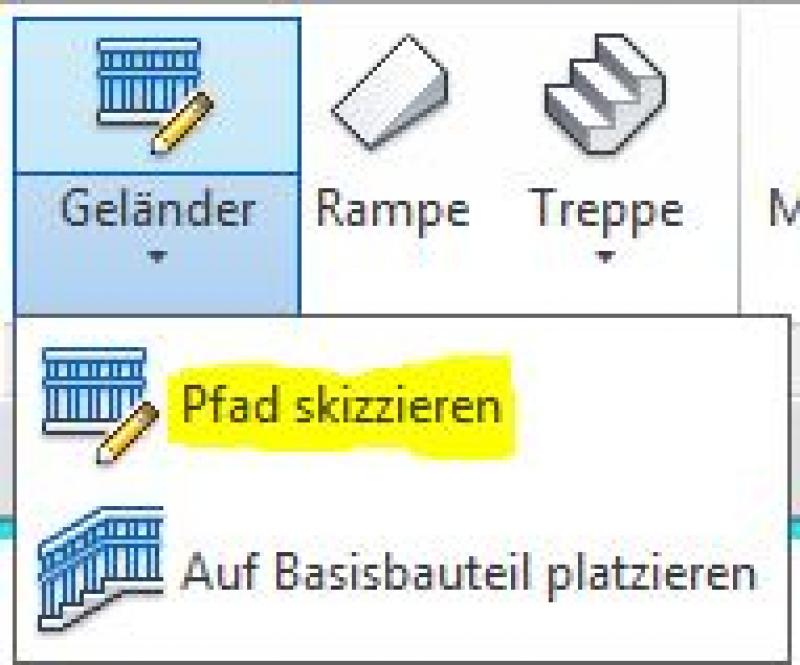
- Define the base for the railing by selecting the command >New Base Component and pointing to the wall that will serve as the base for the parapet. NOTE: This step ensures that the top edge of this wall is defined as a "path" for the railing. If the top edge of the wall is modified, for example using the >Edit Profile command, the railing’s path will also be modified accordingly.
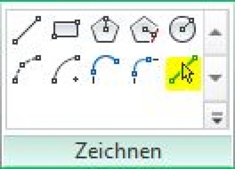
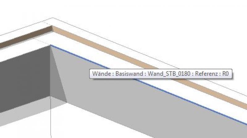
- Use the Drawing Tool > Select Lines to select the corresponding wall edge:
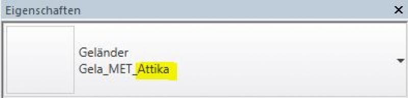
- Assign the prepared parapet railing by selecting the railing type in the Properties window:
Additional information on railing profile families:
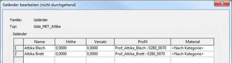
For parapet railing types, 2D profile families with the appropriate cross-sections must be created in advance. Unlike profiles for sweeps or wall sweeps (wall profiles), railing profile families may contain only one line chain (=loop) each. On the other hand, the profile for railings cannot be assigned! For example, it can only contain the outline of a sheet metal development, but not an additional one for the parapet substructure:
However, thanks to the ability to assign any number of profiles (see the following images), users have unlimited design options despite the circumstances described above.
Profiles are assigned in the Type Settings > Railing Design section:
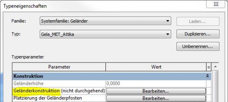
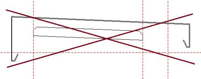
Multiple profiles can be assigned (each line corresponds to a profile):
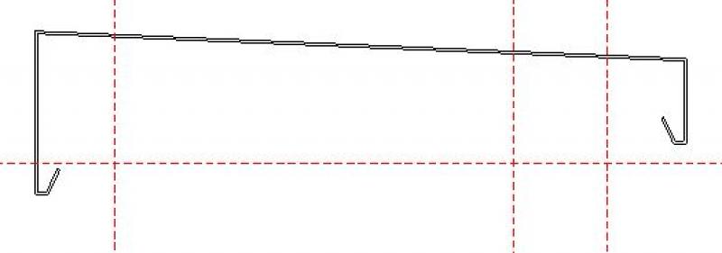
The resulting railing design is geometrically identical to that of the sweep (including mitered corners), but has the advantage that its length can be determined parametrically:
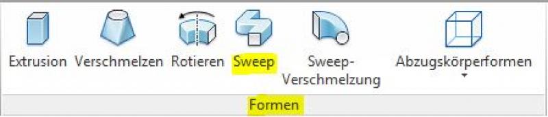
3) Implementation using a project family / sweep:
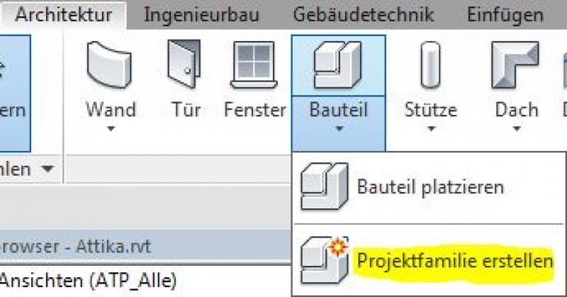
Since Revit does not have a specific command for parapets and they are all elongated objects, it makes sense to create a >project family using the >Sweep command.
Note: Project families are missing important parameters needed for analysis (e.g., length, area, volume, etc.), and they are duplicated in the model when they are copied further.
The following steps are required to model a sweep:
- Command > Architecture > Component > Create Project Family:
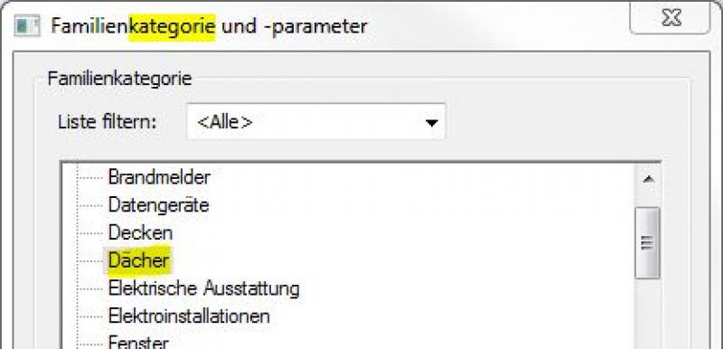
- Category selection (e.g., roofs for parapets):
- Create a shape using the >Sweep command:
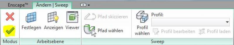
- Select a path using the command >Select Path
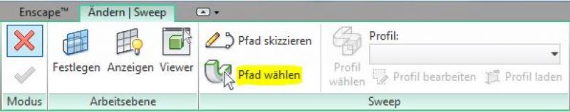
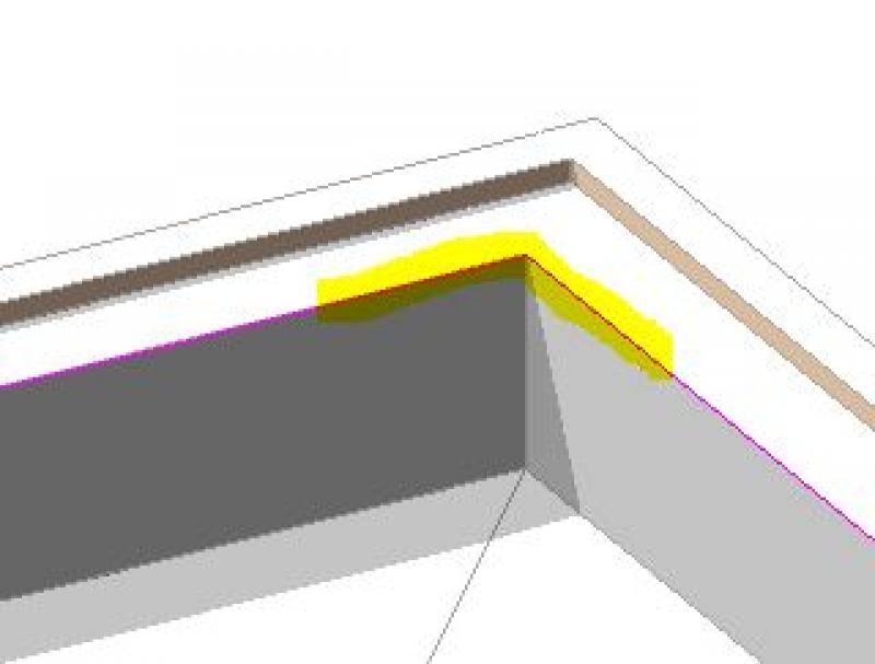
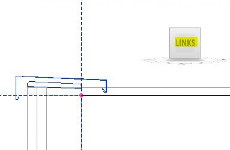
The parapet is typically constructed along a structural parapet wall. Therefore, the corresponding wall edges can be selected as the path:
- Create a profile (cross-section) using the command >
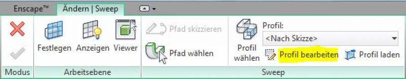
In this case, it is recommended to select a view in which you can draw the cross-section (substructure, sheet metal development, etc.) as you would in an orthogonal view. For example, select a face on the ViewCube that is parallel to the cross-sectional area of the profile:
In any case, it is important to ensure that the profile lines form a closed chain of lines, meaning they contain no gaps and no isolated, unconnected lines.
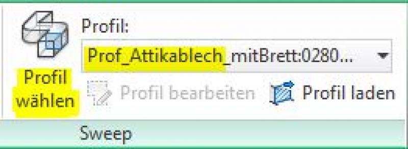
Alternatively, you can use the >Select Profile command to select a profile family (2D family) that was created earlier:
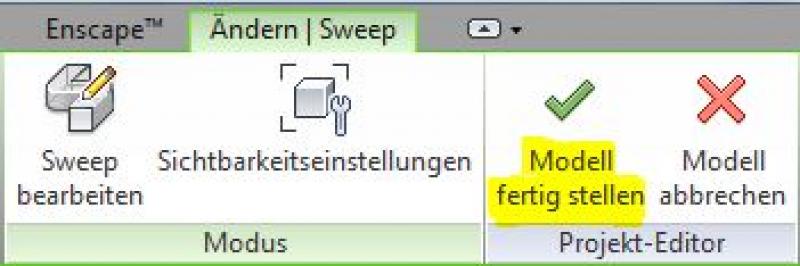
- The final steps are to exit Sweep Creation mode and close the Project Editor—a separate program function used when creating project families (both indicated by a green checkmark):
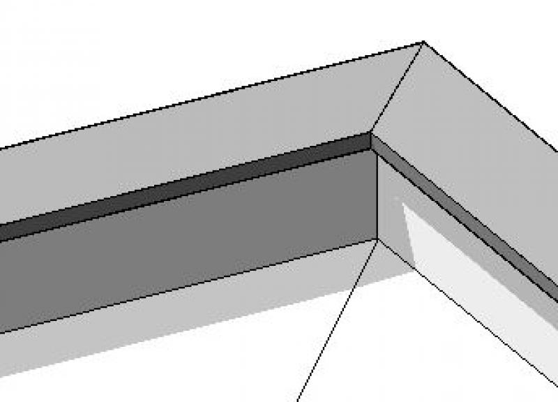
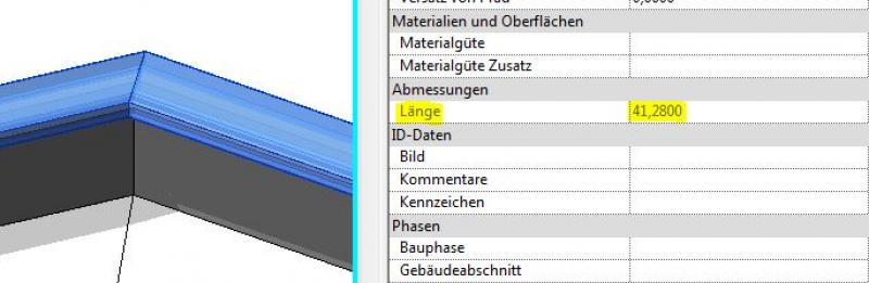
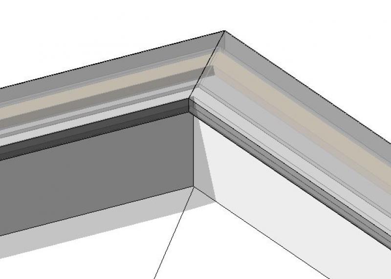
The result of this sweep family is an elongated feature with mitered corners—essentially a "unfolding" of a profile along the selected path:
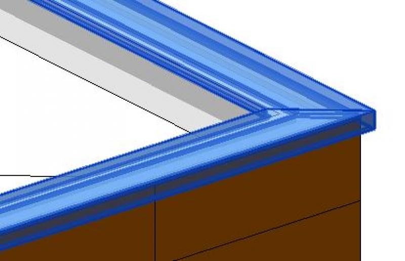
The advantages of this approach are, on the one hand, the relatively simple and straightforward use of the Sweep command and, on the other hand, the virtually limitless design possibilities offered by the shape commands of project families. A disadvantage of using sweeps, however, is that their lengths cannot be read (there is no corresponding parameter). This means that manual reading is required to determine dimensions (see also the section on Revit PRO Kontent in this chapter). In addition, an alternative design for parapets is also recommended:
The basic process of modeling a parapet using the Wall tool in ARCHICAD remains the same throughout the various design phases.
Detailed instructions on walls can be found under "Walls: General."
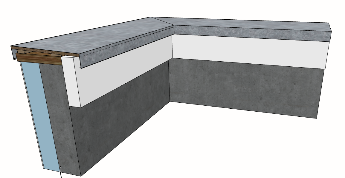
The "Complex Profile" structural method is recommended for structurally complex structures, such as a parapet or a wall with exterior perimeter insulation. It can also be used to model non-full-height cladding in plumbing areas.
An attic consists not only of multiple layers, but also of different types of top and bottom edges. Therefore, modeling it using only a multi-layer component is not sufficient, and the "Complex Profile" structural method is used:
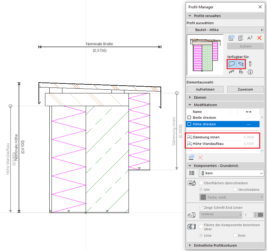
The availability is set to "Wall" because a parapet is modeled using the Wall tool. If the parapet runs along the slope, it can be modeled using the Joist tool. Accordingly, the complex profile should also be made available for joists.
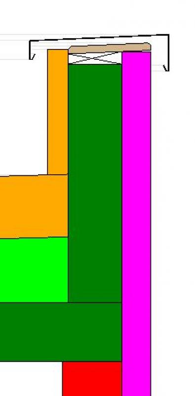
When working with a parapet profile, be sure to set a vertical extension range so that you can adjust the height of the modeled profile. You can create additional modifiers to edit the different insulation types as needed in the 3D space. This eliminates the need to create additional profile variants to accommodate different material thicknesses, as the modifiers allow for real-time adjustments.
In this phase, the building specifications will be updated to include additional information regarding building physics and fire safety.
Presentation
This is where the different countries differ. In Austria, submission plans are color-coded by building material: The representation of the structural components of parapets (e.g., walls) follows the guidelines set forth in the Vienna Building Code.
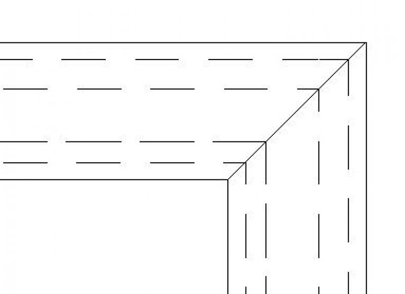
Cut
Floor plan (top view)
Model representation
Cut
Floor plan (top view)
Model representation
Cut
Floor plan (top view)
Model representation
Features
Architecture:
- Fire resistance class
- Construction phase reference
- Reference to construction phase
Other:
- Global Warming Potential (GWP)
- Total global warming potential (GWP)
- Rated sound insulation index Rw
- Lambda value (thermal conductivity)
- Reflectance
- U-value
- Thermal transmittance
Labeling
The labeling of parapets involves the following steps at this stage:
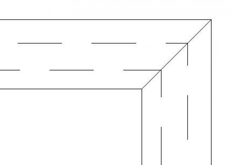
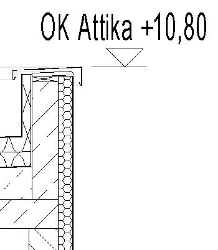
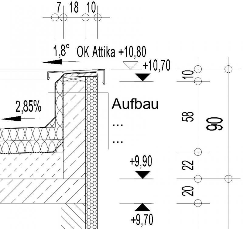
- Finished parapet top edge in cross-section (top of parapet above ±0.00 of the building)
- Structure designation according to the component catalog
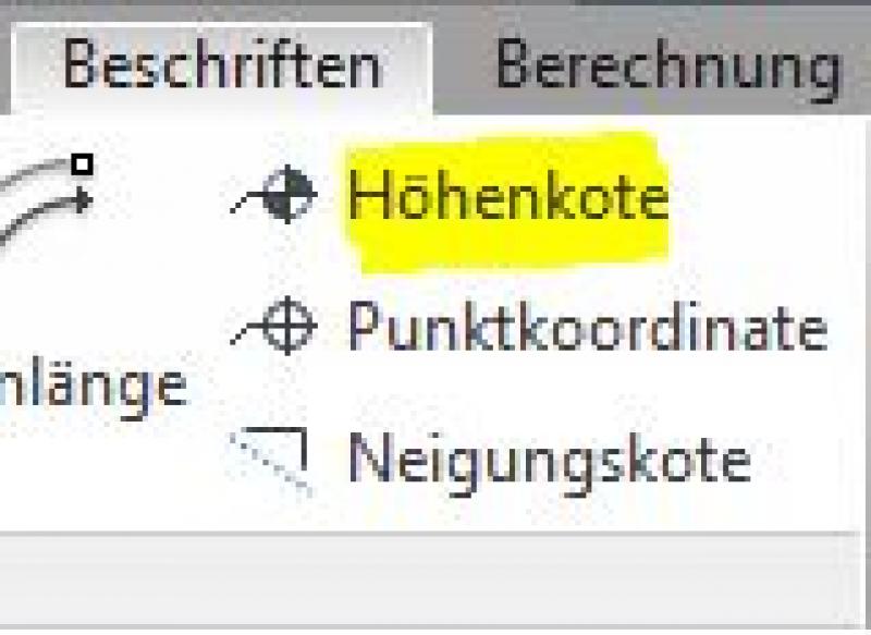
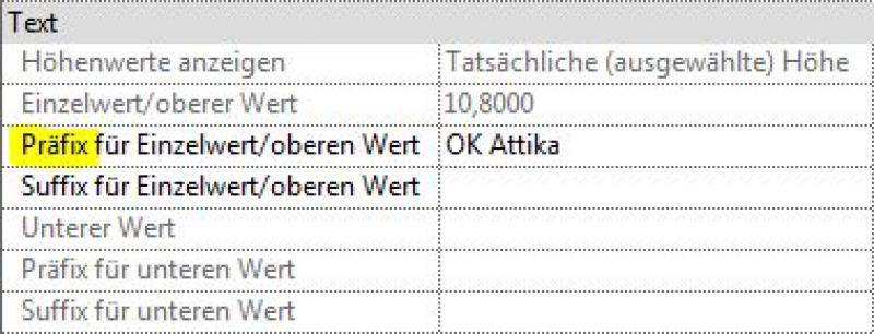
The top edge of the parapet can be created in the section using the >Label >Elevation command:
For elevation marks that are to be placed next to the object, it is necessary to place a leader line using the >Label >Leader command.To label the elevation (e.g., OK Attica), enter the desired text in the Properties window under the >Prefix for... entry:
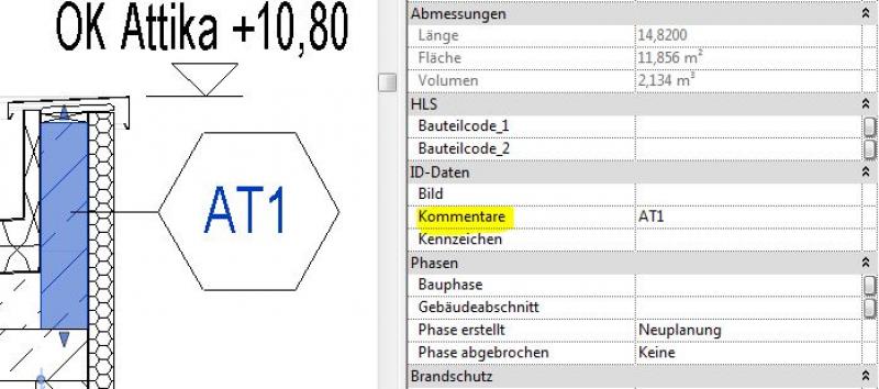
The structural components of the parapet are labeled with their assembly codes as specified in the component catalog. Example for the wall component: "AW01" (for exterior wall 01)
Note:All structural types must be labeled manually and, if necessary, verified. This means that, ideally, the labeling should be performed using a family that retrieves the necessary information from the parameters and properties of the structural components (see the example of a wall below):
Commands for labeling: >Label >Label by Category or >Label All:
The new features and parameters for this phase must be added in the appropriate sections of the component's settings dialog.
A description of the settings dialog and the corresponding procedure can be found in the article "Wall: General" or in an earlier section of this article.
The labeling and dimensioning of the component should always be done associatively. Instructions on how to do this in ARCHICAD can be found in the relevant articles.
Instructions
During this phase, the Department of Architecture provides all the building physics data required for calculations in the permitting phase. For parapets, the primary focus is on the structural components. For more information, see the relevant articles listed in the “Conceptual Preliminary Planning” section.
During this phase, all information required for the design of parapets in accordance with standards and for their professional procurement is compiled. This generally includes all information relevant to design and tendering, including any manufacturer-specific details.
Presentation
Cut
Floor plan (top view)
Model representation
Features
Costs: ÖNORM B1801 classification, DIN KVPAPGE classification, element number, eBKP-H classification, BOA-BKG classification, formwork area, BOA component code (type comment)
Labeling
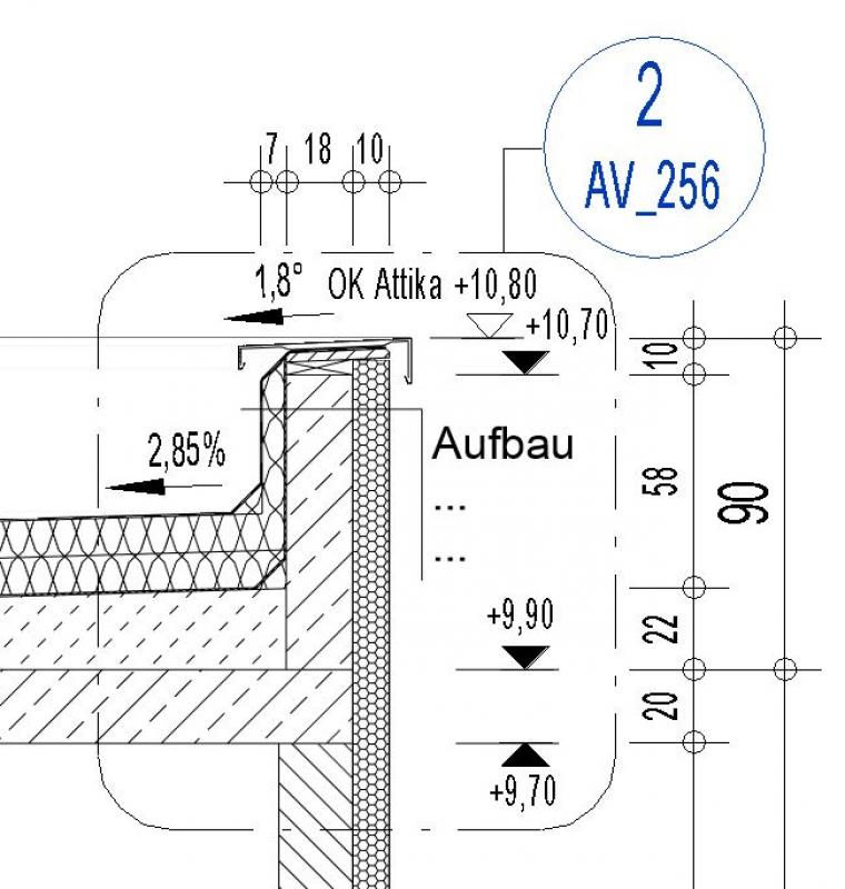
The labeling of parapets involves the following steps during this phase:
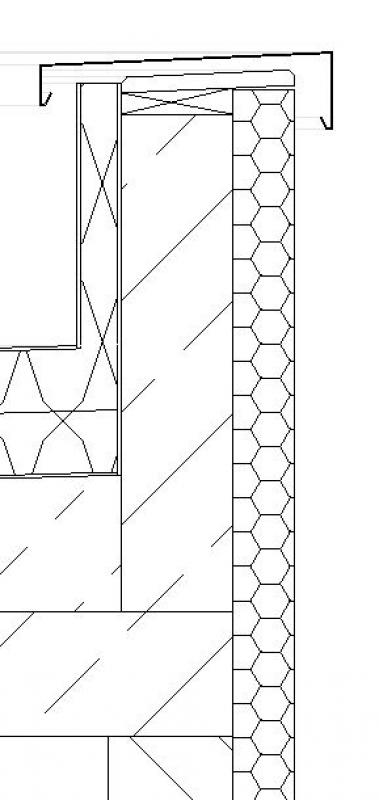
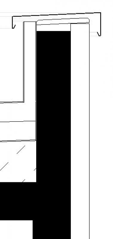
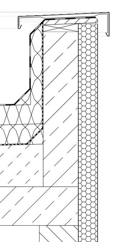
- Shell structure and finished top edges in section
- Dimensions of the shell components in plan and section
- Cross-section of the shell parapet’s layered structure
- Slope of the covering in cross-section, if applicable
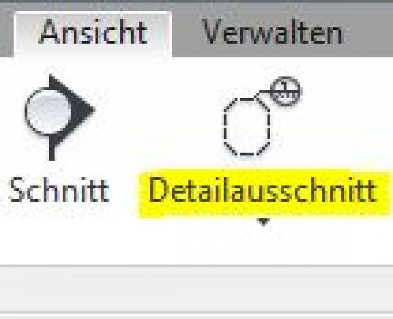
The labeling tasks are performed in Revit using these commands:
- Top edges of parapets: Command >Label >Elevation
- Dimensions of structural components: Command > Label > Aligned Dimension
- Layer structure: Command > Label > Text or extract text from component parameters
- Slope of covers: Command > Label > Slope elevation
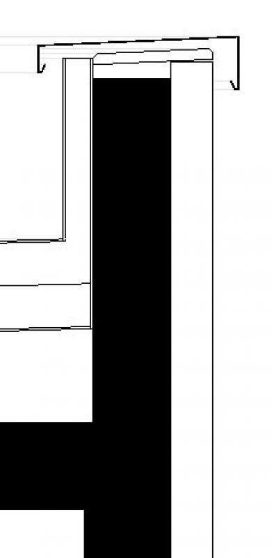
Detail of a sectional view (scale 1:50) Floor plan
The new features and parameters for this phase should be added to the appropriate sections of the component's settings dialog.
A description of the settings dialog and the corresponding procedure can be found in the article "Wall: General" or in an earlier section of this article.
The labeling and dimensioning of the component should always be done associatively. Instructions on how to do this in ARCHICAD can be found in the relevant articles.
Instructions
The decisions regarding reinforcement made during this phase are provided by the structural engineering department and incorporated into the structural components of the parapets.
The information regarding detailed design decisions made during this phase is provided by the Architecture and AVA departments and incorporated into the detailed design. It is strongly recommended that this elaboration be carried out not in a 3D model but in a 2D detail with a corresponding note on the plan.
Revit offers a range of features for creating construction details. However, the first step in this process should always be to switch from 3D modeling to 2D detailing. The command for this in Revit is >View >Detail
The new features and parameters for this phase must be added in the appropriate sections of the component's settings dialog.
A description of the settings dialog and the corresponding procedure can be found in the article "Wall: General" or in an earlier section of this article.
The labeling and dimensioning of the component should always be done associatively. Instructions on how to do this in ARCHICAD can be found in the relevant articles.

Unfortunately, this content is available only to our Pro users.
If you'd like to read the full article, try the Pro account or become a Pro user.