Along with doors, windows represent the most complex object types in BIM workflows for building construction. Extensive requirements set forth in drawing symbol regulations regarding graphical representation by scale and phase, a wide range of necessary settings for geometry, installation type, and the handling of any accessories, such as window sills or shading elements, make windows complex computational objects. Here, the various BIM programs differ very significantly in their handling and performance capabilities.
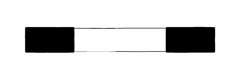
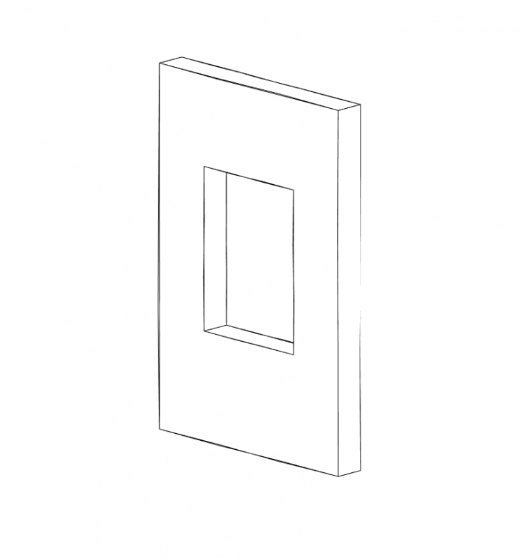
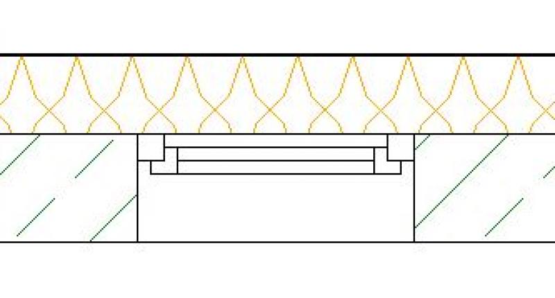
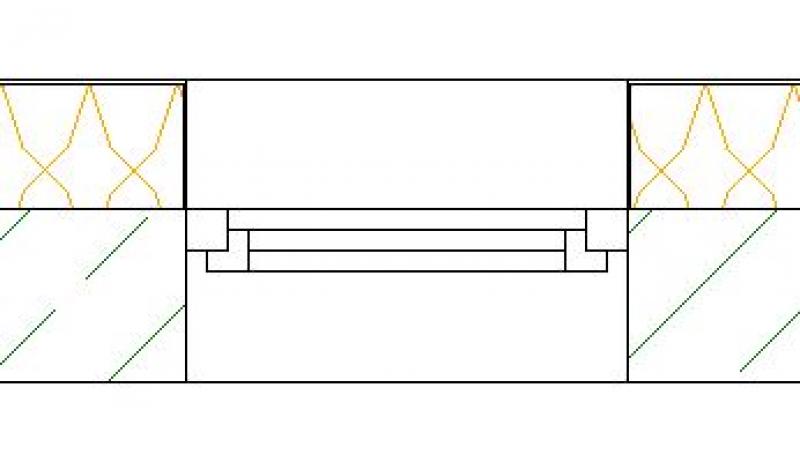
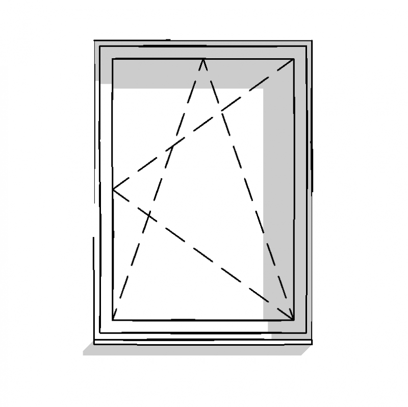
At this stage, windows are typically represented only abstractly as simple openings in the building envelope. This means that the model does not necessarily have to include specific window objects.
Presentation
Plan view
Model representation
Features
Feature
- Reference
- Status
Parameters
- Wide windows
- Parapet height
- Window height
Outline Information
- External element
Labeling
At this stage, windows are not yet labeled in plan views.
Instructions
Generally speaking, there are two main ways to create abstract window openings in Revit:
1) The required cutouts are created using the opening functions:
Command: >Architecture >Openings command group >Wall (in walls), >Shaft (for skylights in roofs)
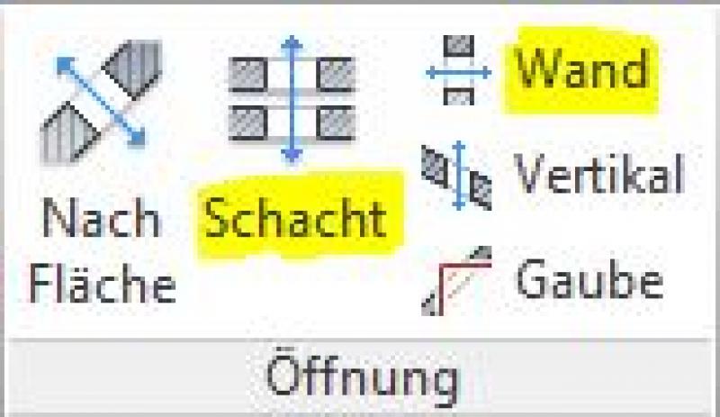
While these commands make it very easy to create an opening in a part, they do not provide the corresponding dynamic labeling or the typical symbols used for openings. For this reason, the second method is ultimately recommended:
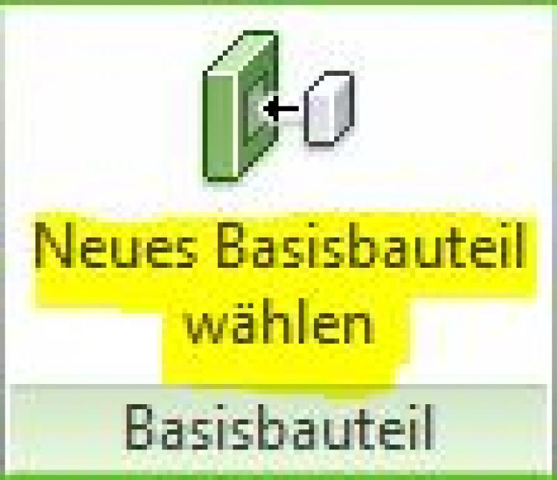
2) Window openings are created using external (i.e., "loadable") window families designed specifically for this purpose:
These consist essentially only of cut-out elements (hollow "negative elements") that cut out the necessary openings from basic components such as walls or roofs. In such cases, these are referred to as “wall-based” or “roof-based” components.
Abstract window opening families can be found in the Revit Content library. New window opening families must be created using the family template file >M_Window.Further instructions on creating openings as described in point 1) can be found in the article Openings - Cutouts - Slots. Further instructions on creating windows as described in point 2) can be found in this article under the section >Preliminary Planning >Instructions.
The element classification is the first definition in the field
Classifications
and characteristics – see also
Classification. When you select a classification in the window, only those properties relevant to that classification—as defined by the IFC properties—are displayed in the lower section of the field.
and according to the Properties Manager
are available.
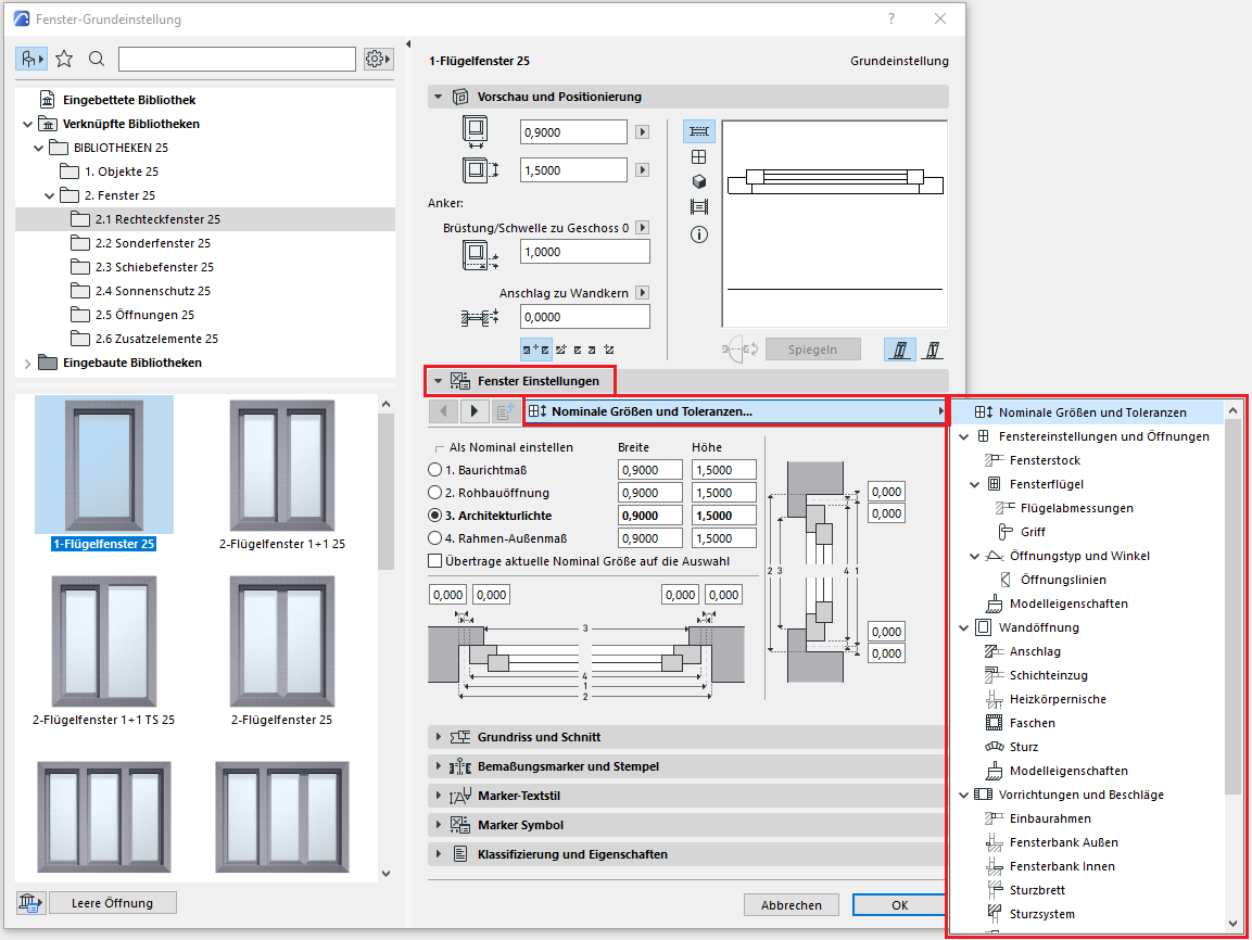
Figure 7
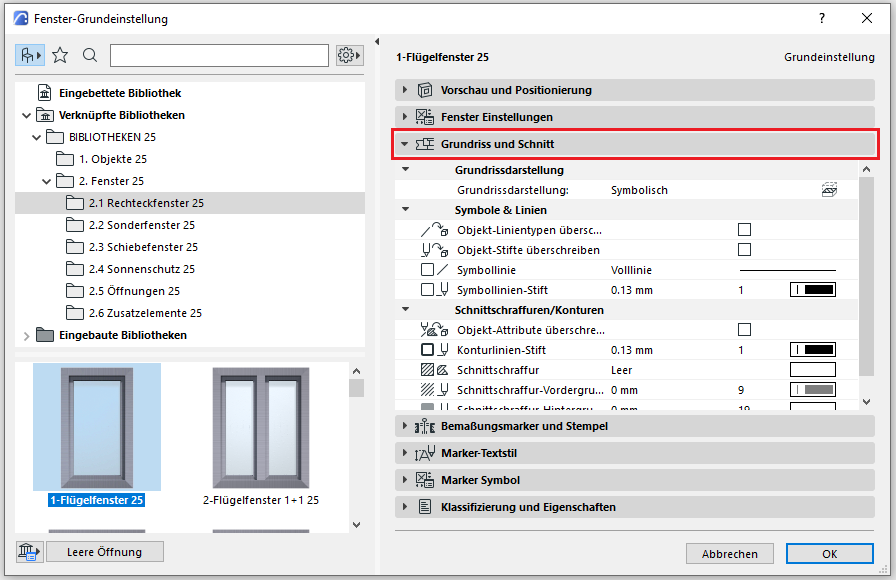
Figure 8
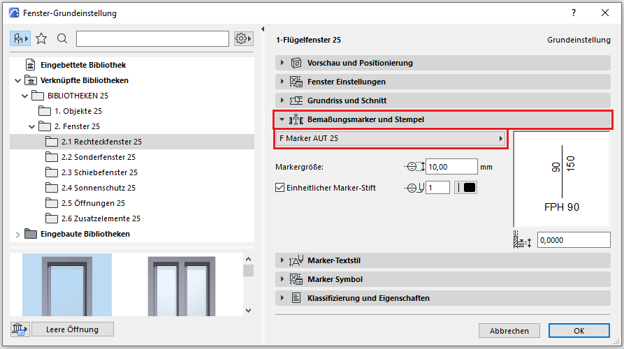
Figure 9
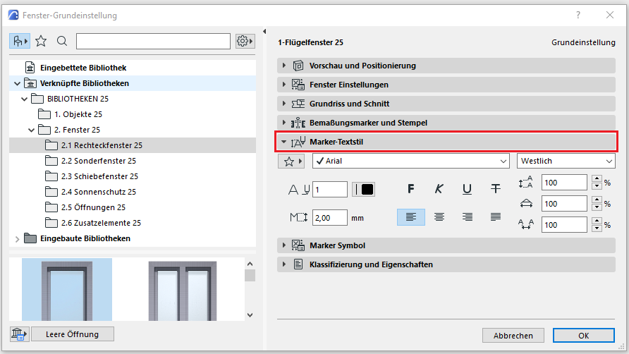
Figure 10
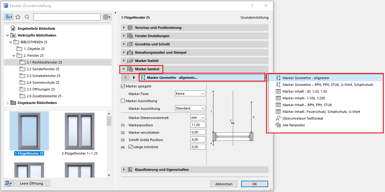
Figure 11
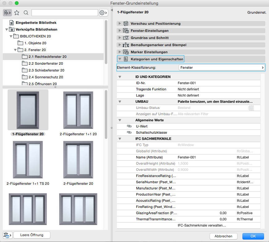
Figure 12
In this phase, windows are created for the first time using specially designed 3D objects, and a material is assigned to the components.
Presentation

Plan view
Model representation
Features
- Escape route
Parameters
Outline Information
Labeling
At this stage, windows are not yet labeled in plan views.
Instructions
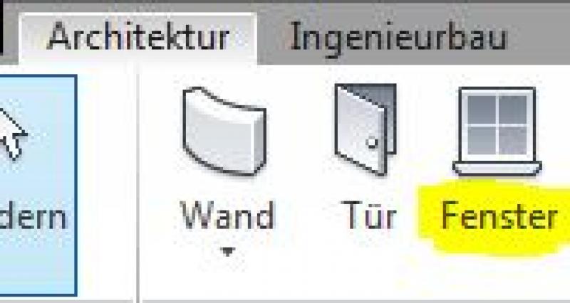
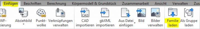
In Revit, windows belong to the category of the same name and are created using the command >Architecture >Window. Since they do not belong to the system families palette but rather to the so-called external (i.e., "loadable") families, they must be loaded from Revit Content as needed using the >Insert >Load Family command:
Command for windows:
Command for loading window families:
Classification of window families:
The window content included with Revit is logically organized into families, with the family names indicating the number of sashes or the window’s division. For example, there are single-sash, double-sash, and multi-sash (or multi-panel) windows. In addition, corner windows and French doors are available in separate families.
Window placement:
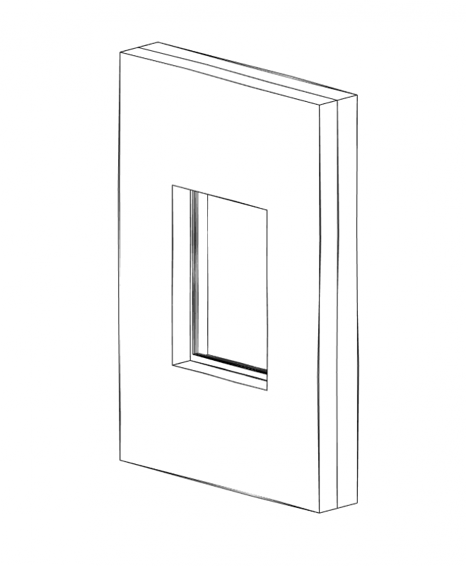
Most window families in Revit are designed so that they can only be placed in walls. In such cases, these are referred to as “wall-based” families, meaning that the base element must be a wall. Exceptions include window families that are intended for installation in facades and are named accordingly.
Windows are typically offset within a wall in floor plans. The advantage over placing them in axonometric projections, perspectives, or other views is that this allows both the positioning relative to other objects in the floor plan and the selection of the base component when there are multiple walls stacked layer upon layer (as is common in hybrid construction). On the other hand, placing windows in building views could be advantageous for potential facade design.
In summary, it can certainly be said that offsetting in the floor plan followed by a shift in a view is a perfectly viable approach to window modeling.
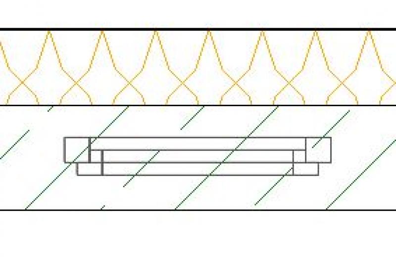
Placement of windows when using the hybrid modeling method:
The following specific approach should be used when applying the hybrid modeling method:
1) Because the hybrid modeling method involves multiple separate walls placed side by side in the floor plan, you should first select the wall where the window is to be placed. To do this, move the cursor over a wall axis to display a preview of the window.
2) Click on a wall to install the window. The hinge side of the window can be changed later using the "double-arrow icons" (control element/double vertical).

or the base wall can be replaced using the >Select New Base Component command:
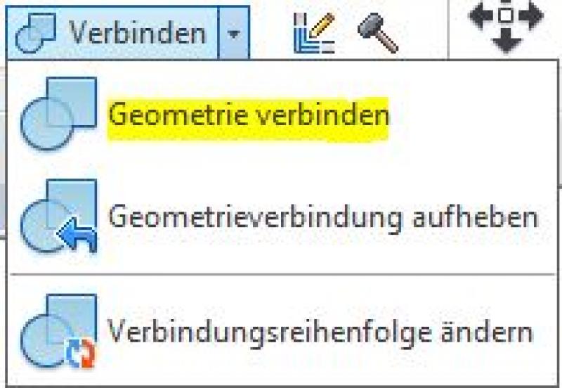
3) Finally, the opening "information" (the opening in the shell) is transferred from the base wall component to other walls (e.g., insulation walls or wall coverings). To do this, use the command >Modify >Connect >Connect Geometry:
Example: Window placement in buildings with multiple walls (hybrid construction)
1) Select wall 2) Install window 3) Connect geometry
Parameterization of window families:
The performance of a window family (and families in general) depends largely on the parameterization and level of detail of the built-in geometries. In this regard, there are sometimes significant differences among various family manufacturers, which is why it is difficult to make a general statement on the matter. In Revit, the general rule is: Anything is possible, but too much is too much (H. Reichholf). In any case, to ensure the best possible program performance, it is strongly recommended that you avoid using families with highly complex formulas in their parameterization and highly detailed geometries!
For the reasons mentioned above, the brief description below is limited to the standard parameterization of window families:
Type parameters:
- Width / Rough-in width: Determines the rough-in dimension of the window width
- Height / Rough-in height: controls the rough-in dimension of the window height
- Various parameters for frame or sash dimensions
Instance parameters:
- Level: refers to the installation level to which the window is referenced (usually: FBOK = top of floor)
- Sill/Parapet: is the height from the installation level to the bottom edge of the window (RPH = rough-in parapet height)
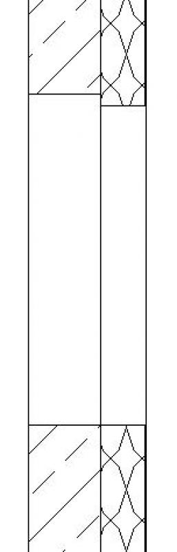
- Installation depth: Position of the window within the wall depth (or reveal)
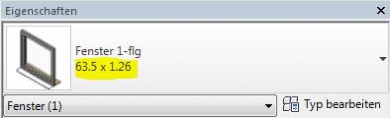
Changing a window type:
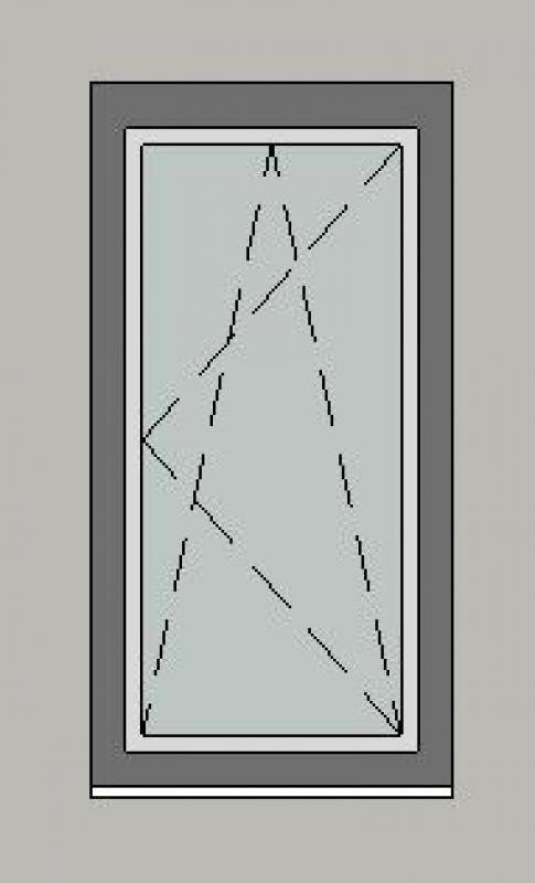
In the Properties window, you can select the type that is typically responsible for the window size using the type parameters described above:
Window size depending on the selected type (example illustration at a scale of 1:50):
Additional information:
- Windows should always be placed on a single layer to avoid elevation errors later on
- The material is assigned via instance parameters.
- Windows and doors must always be placed in the same wall; otherwise, a circular reference will occur with connected elements.
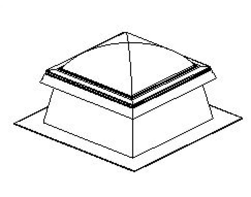
- Exceptions are skylights, as they are placed in roofs and not in walls. For skylights, the same workflow is applied to the roof component.
For information on creating new families, see the article "Building Families."
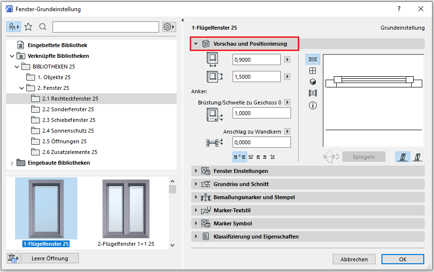
The basic process of modeling a window in ARCHICAD remains the same throughout the various design phases.
The new features and parameters added for this phase must be entered in the appropriate fields of the component's settings dialog.
The description of the settings dialog and the corresponding procedure can be found in an earlier section of this article.
The labeling and dimensioning of the component should always be done associatively. Instructions on how to do this in ARCHICAD can be found in the relevant articles.
In this phase, surface materials are assigned to the windows, building physics properties are added, and the most important dimensions are added to floor plans and sections.
Presentation
This is where the different countries differ.
Figure 1
G_3d
Figure 1
G_3d
Figure 1
G_3d
Features
Feature
- Window Type
- Fire resistance class
- Position of sunshade
- Smoke protection
- Window frame
- Block frame
- Sash frame
Parameters
- Thick posts
- Thick transoms
- Wide outer frames
- Thick sash frames
- Height of outer frame
Outline Information
Labeling
In this phase, the window dimensions (shell dimensions) are labeled on the floor plan, and the top edge of the parapet and, if applicable, the bottom edge of the lintel are labeled on the section view.
Window labels can be obtained from Revit Content. New labels are created using the label family template >M_WindowLabel. The labels to be added at this stage can be implemented in Revit as follows:
- Window labels in the floor plan are added using the command >Label >Label by Category or >Label >Label All.
- Window labels in sections are created using the command >Label >Elevation.
The basic process of modeling a window in ARCHICAD remains the same across the various design phases.
The new features and parameters for this phase must be added in the appropriate sections of the component's settings dialog.
The description of the settings dialog and the corresponding procedure can be found in an earlier section of this article.
The labeling and dimensioning of the component should always be done associatively. Instructions on how to do this in ARCHICAD can be found in the relevant articles.
Instructions
The Department of Architecture will provide surface definitions and building physics properties.
Materials are entered using the corresponding parameters in the Properties window:
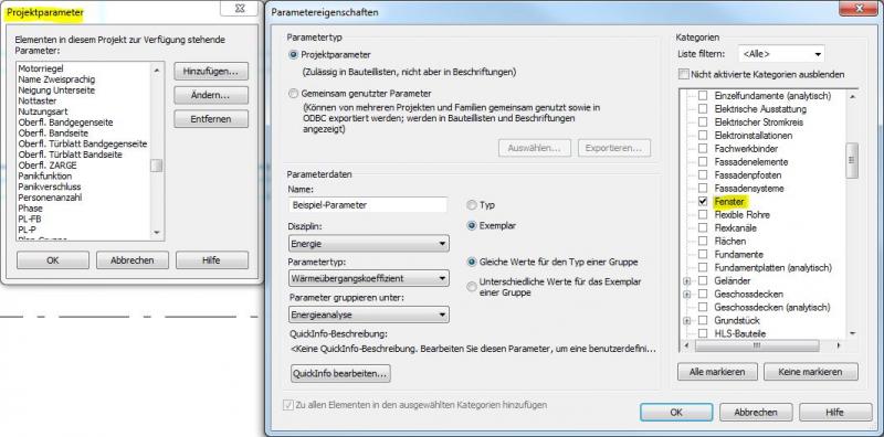
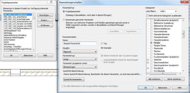
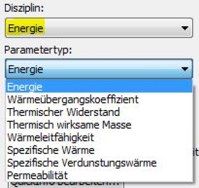
Building physics properties are entered using special parameters that can be created via the >Manage >Project Parameters command:
The basic process of modeling a window in ARCHICAD remains the same across the various design phases.
The new features and parameters for this phase must be added in the appropriate sections of the component's settings dialog.
The description of the settings dialog and the corresponding procedure can be found in an earlier section of this article.
The labeling and dimensioning of the component should always be done associatively. Instructions on how to do this in ARCHICAD can be found in the relevant articles.
During this phase, windows are labeled as "approval-ready" and supplemented with additional information regarding building physics and fire safety.
Presentation
This is where the different countries differ. In Austria, submission drawings are color-coded by building material: The representation of walls (the basic components of windows) follows the guidelines set forth in the Vienna Building Code.
Figure 1
G_3d
Figure 1
G_3d
Features
- Total Solar Energy Gain
- Proportion of glass area
- Light transmittance
- Sound insulation class
- U-value
- Uf-value [W/m²K]
- Heat transfer coefficient Uw [W/m²K]
Parameters
Outline Information
Labeling
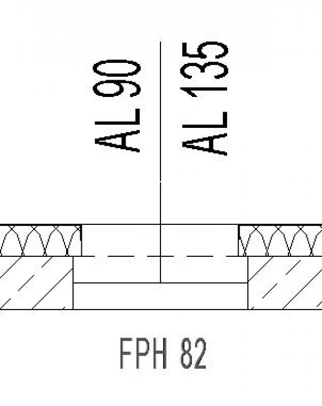
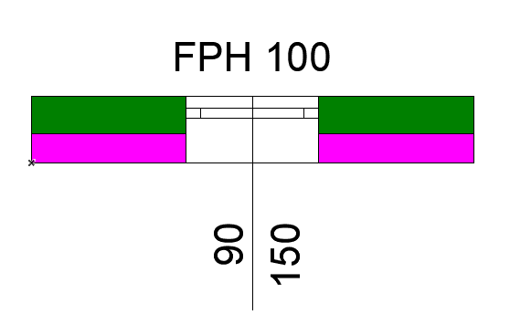
Window labeling in this phase includes the following measures (see, for example, Ö-NORM A_6240-2, Section 9.6):
- Window dimensions in the floor plan (AL = architectural opening on the window axis)
- Top edge of the parapet in the floor plan (FPH = finished parapet height above FBOK = top edge of the floor)
- If applicable, window edges or top edges of the lower frame (fall protection)
Window labels can be obtained from Revit Content. New labels are created using the label family template >M_WindowLabel. The labels to be added at this stage can be implemented in Revit as follows:
- The architectural dimensions of the window in the floor plan (on the axis) are added using the >Label >Label by Category command or the >Label >Label All command.
- Top edges of parapets (finished parapet heights):
When using FBOK reference heights (= floor top level) for the respective floor, these must be indicated with text in the floor plan and section (Reason: Unfortunately, Revit does not allow for the definition of other reference heights, which would be the case, for example, with the parapet height)
When using reference heights relative to the building’s ±0.00, these can be created in the floor plan and section using the command >Label >Elevation. However, care must be taken to select the correct height on the window sill (for finished parapet heights, the top edge of the window sill should be selected). Additionally, the >Show Elevation Values setting in the Options bar must be considered when selecting the correct elevation: The options are: Top Elevation / Bottom Elevation / Top and Bottom Elevation
You can label a window using the marker in the settings dialog.
Instructions
During this phase, the Department of Architecture provides all the building physics data required for the calculations in the permit application process.
Building physics properties are entered using special parameters that can be created via the >Manage >Project Parameters command:
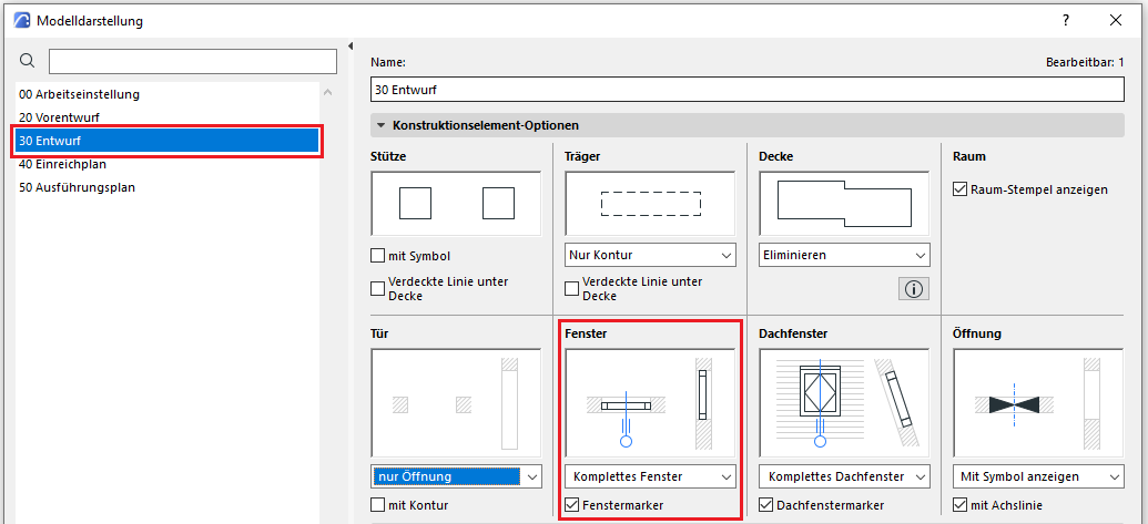
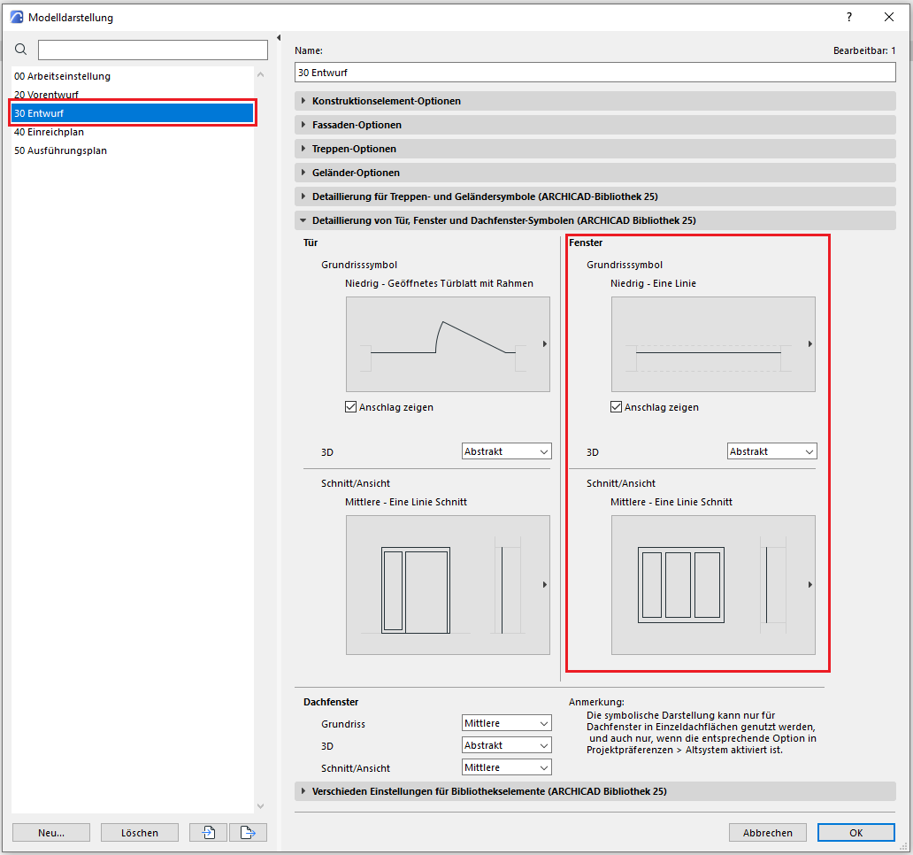
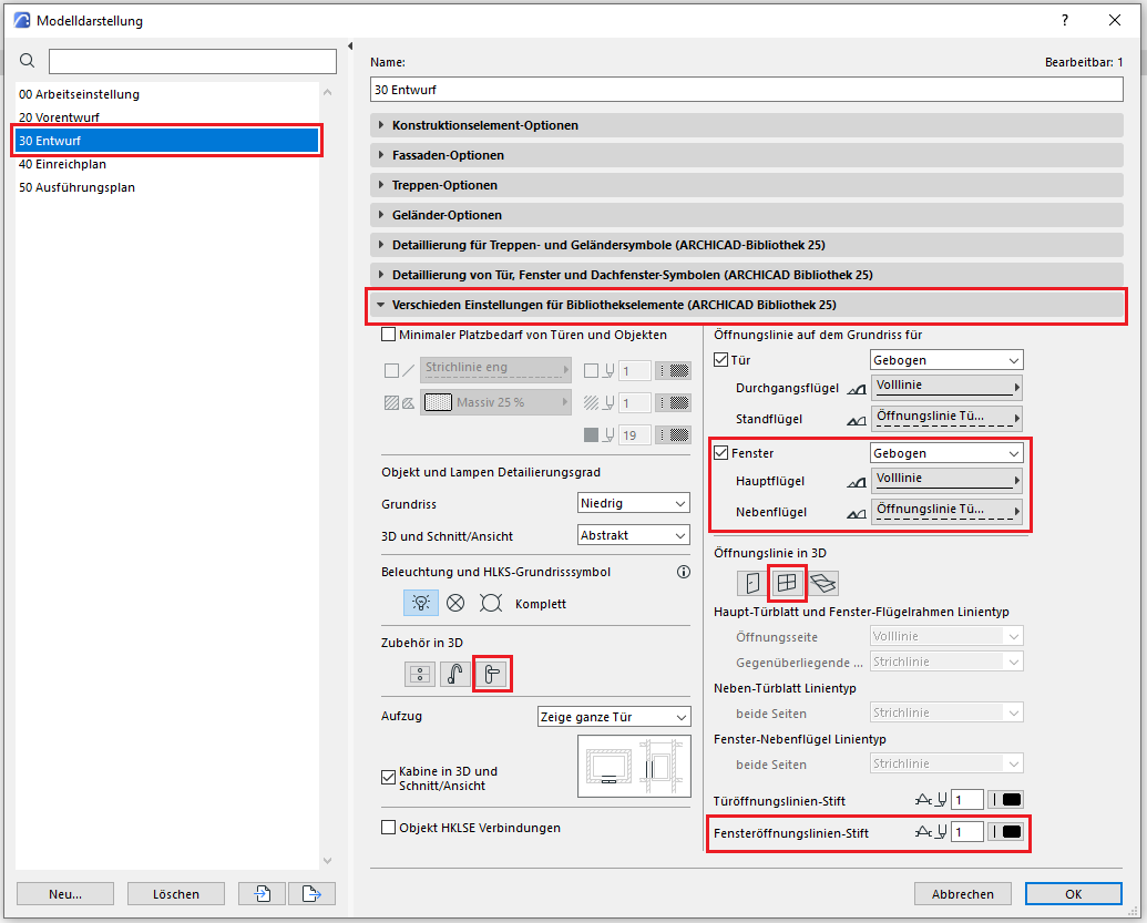
The level of detail for windows can be adjusted according to the phase using the model display options. An important prerequisite is that the 2D and 3D display options in the window element settings have been set to “According to model display.” The following settings should be applied during the submission phase.
In the "Window Icons Details" tab, select the following settings to choose the appropriate icon for the submission
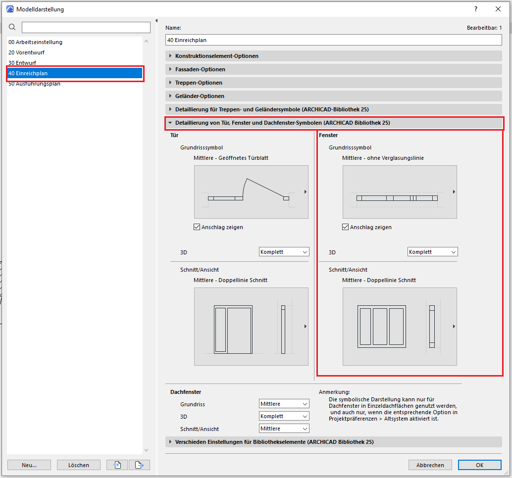
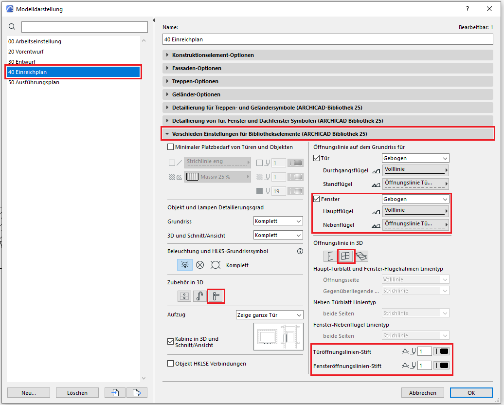
In the tab containing the various library object settings, you should disable the accessories and opening line to keep the window appearance schematic.
The new features and parameters for this phase must be added in the appropriate sections of the component's settings dialog.
The description of the settings dialog and the corresponding procedure can be found in an earlier section of this article.
The labeling and dimensioning of the component should always be done associatively. Instructions on how to do this in ArchiCAD can be found in the relevant articles.
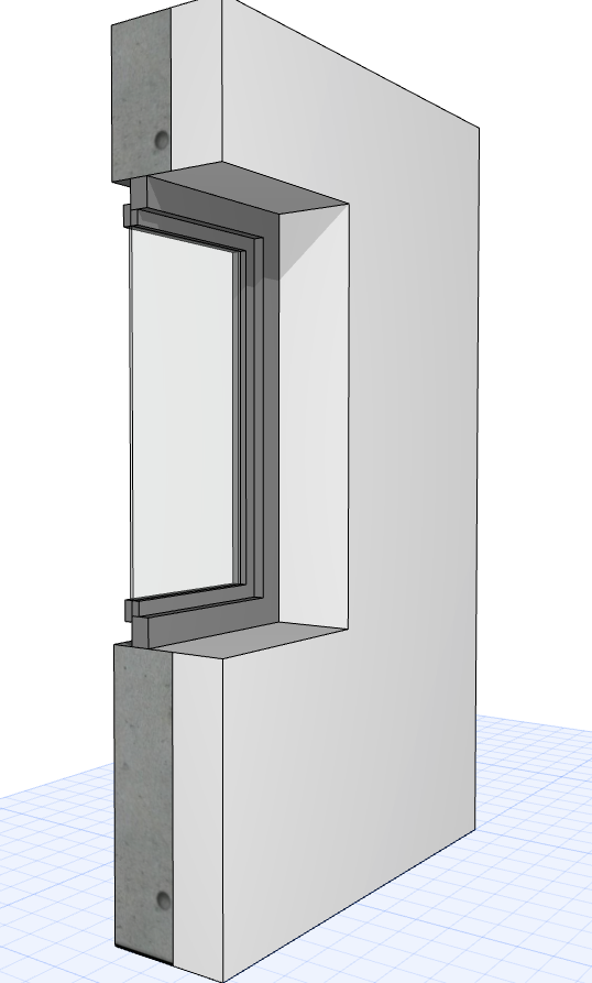
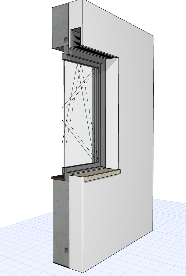
During this phase, all information required for standard-compliant construction planning and the proper awarding of contracts for windows is compiled. This generally includes all details relevant to construction and tendering, including any manufacturer-specific information.
Presentation
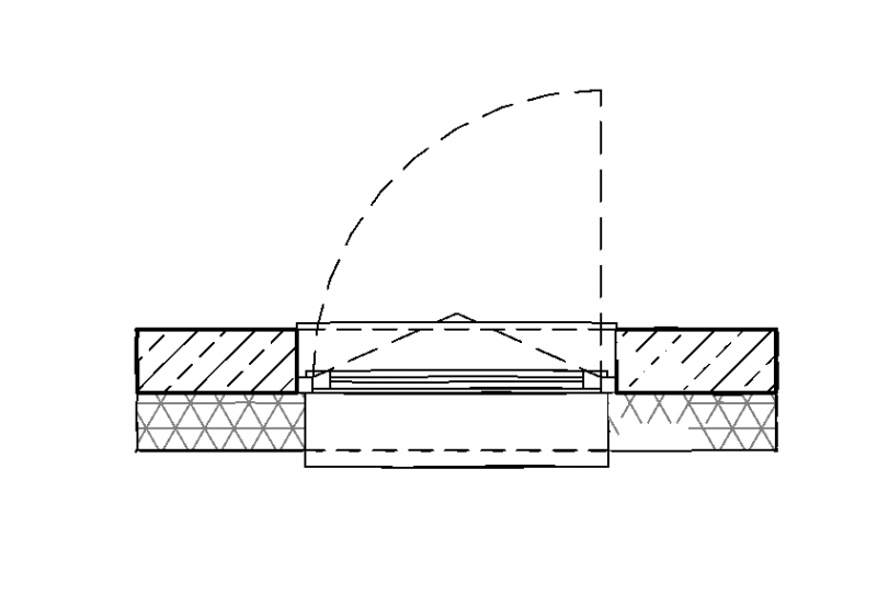
Floor plan
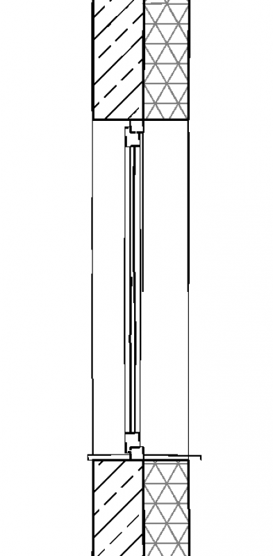
Plan view (cross-section)
Plan view
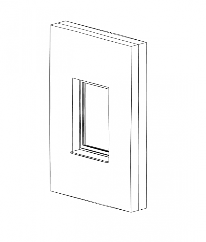
Figure 4
Features
Feature
- Drive
- Weather protection profile design
- Exterior window sill
- Interior window sill
- Air permeability
- Weather protection profile
- Resistance class
- Manufacturer
Parameters
- Wide architectural openings
- Width of sash outer dimension
- Width of wall opening
- Width of floor opening
- Width of floor opening
- Frame thickness
- Sash frame thickness
- Architectural opening height
- External sash height
- Wall opening height
- Exterior floor height
- Clear opening height
Outline Information
Labeling
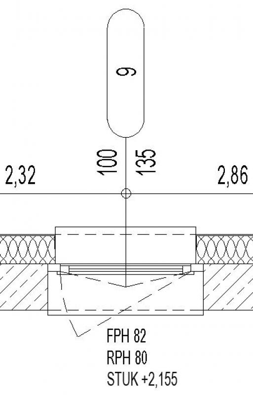
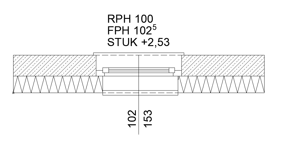
Window labeling in this phase includes the following measures (see, for example, Ö-NORM A_6240-2, Section 9.6):
- Window dimensions + window number on the floor plan (RBL = clear opening at window axis)
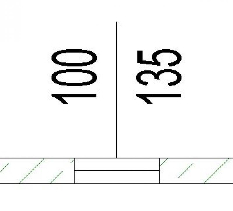
- Top edges of parapets in floor plan + section (FPH = finished parapet height above FBOK = floor top edge, RPH = rough-in parapet height above RDOK = rough ceiling top edge)
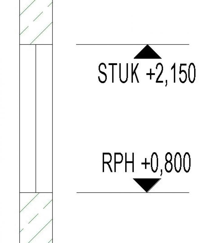
- Window lintel heights (STUK = bottom edge of lintel above 0.00)
Window labels can be obtained from Revit Content. New labels are created using the label family template >M_WindowLabel. The labels to be added at this stage can be implemented in Revit as follows:
- Window dimensions in the floor plan (on the axis) are labeled using the >Label >Label by Category command or the >Label >Label All command.
- Top edges of parapets and bottom edges of lintels:
When using reference heights FBOK (floor top) and RDOK (rough ceiling top) for the respective floor, these must be indicated with text in the floor plan and section (Reason: Unfortunately, Revit does not allow for the definition of other reference heights, which would be the case, for example, with the structural height.)
When using reference heights relative to the building’s ±0.00, these can be created in the floor plan and section using the command >Label >Elevation. However, care must be taken to select the correct height on the window sill (for finished parapet heights, the top edge of the window sill should be selected). Additionally, the >Show Elevation Values setting in the options bar must be considered when selecting the correct elevation: The options are: Top Elevation / Bottom Elevation / Top and Bottom Elevation
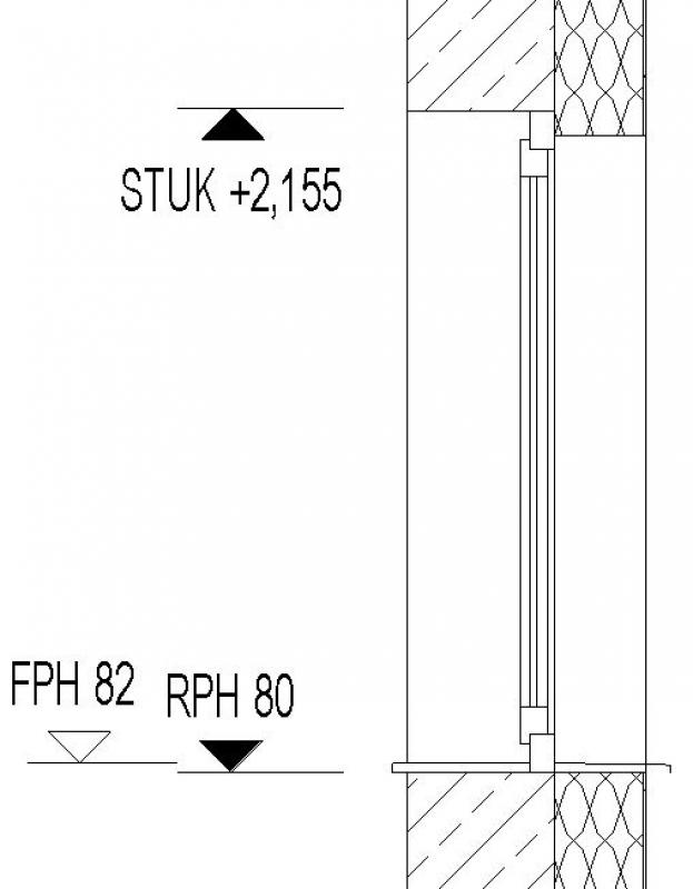
Floor plan: Axis with window number Section
FPH = finished parapet height
RPH = Parapet height of the building shell
STUK = bottom edge of the lintel
Instructions
Of course, the options for displaying windows depend on the level of detail in the respective family. The Revit content offers a wide range of well-designed families in this regard.
However, when selecting families, the following factor should always be taken into account:
Special note regarding the selection of window families (and families in general):
Modelers often make the eager—though not necessarily effective—attempt to add window details to the family at this stage. As a result, this frequently leads to a very extensive and time-consuming family design process.
However, given the need to abstract building components in the BIM environment and taking Revit performance into account, it is strongly recommended to create detailed drawings of windows (and other building components) using 2D details with corresponding floor plan references is strongly recommended!
The level of detail for windows can be adjusted according to the phase using the model display options. An important prerequisite is that the 2D and 3D display options in the window element settings have been set to “According to model display.” In the Execution phase, the following settings should be applied.
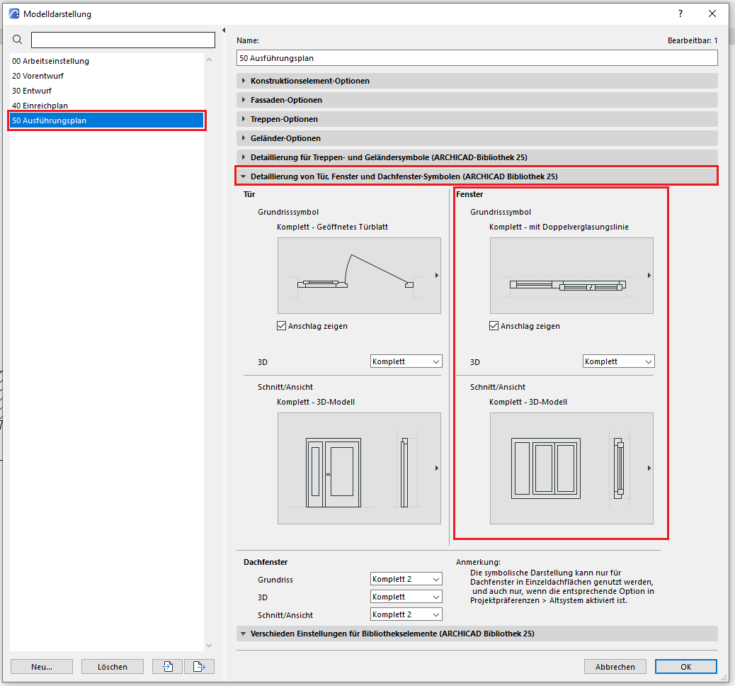
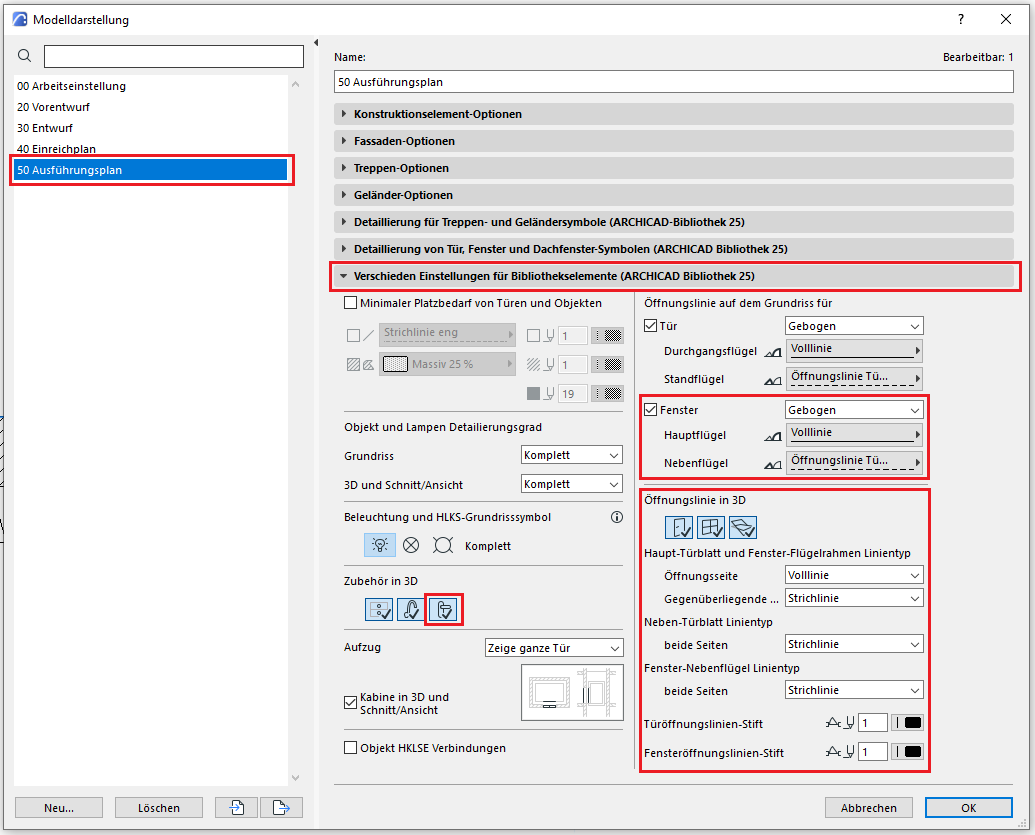
In the tab containing the various library object settings, you should display the accessories and the opening line.
The new features and parameters added for this phase must be entered in the appropriate fields in the component's settings dialog.
The description of the settings dialog and the corresponding procedure can be found in an earlier section of this article.
The labeling and dimensioning of the component should always be done associatively. Instructions on how to do this in ArchiCAD can be found in the relevant articles.

Unfortunately, this content is available only to our Pro users.
If you'd like to read the full article, try the Pro account or become a Pro user.