Finished floors include all floor layers that are not part of the building shell. These include, for example, traditional floor systems with floating screed, raised floors, and double floors, as well as coatings on underground garage ceilings.
The modeling method for floor structures is based on the general strategy for handling multi-layer components. In most cases, however, floors are modeled as multi-layer components separate from the raw slab, because this facilitates room-by-room work, labeling, and evaluation. (This is referred to as hybrid modeling.)
At this stage, floors rarely appear as separate elements and are typically defined as part of an overall floor package (for more information, see the multi-layer modeling approach). This reduces the effort required for modeling and making changes.
Presentation
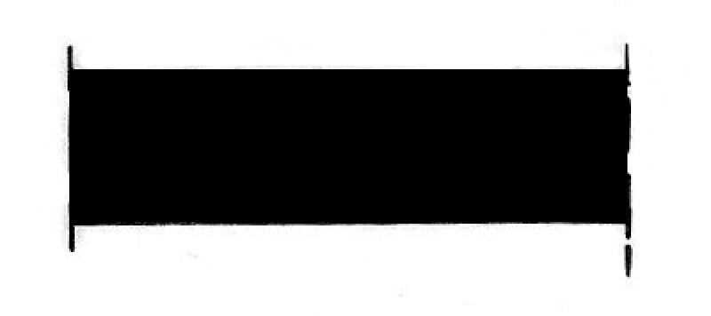
Plan view
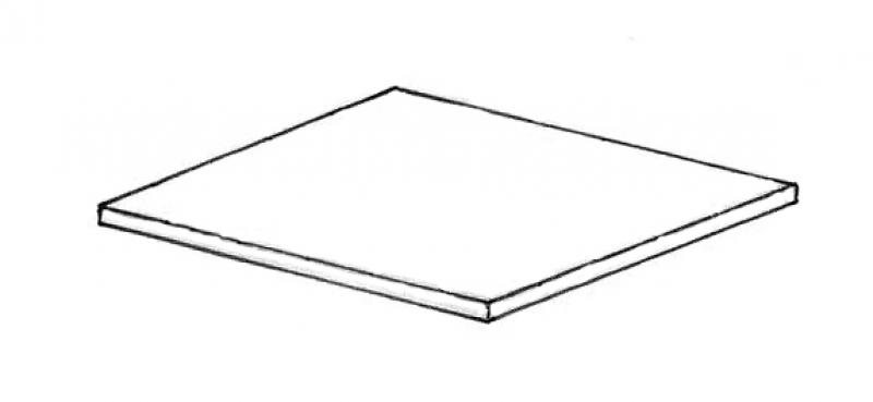
Model representation
Features
Feature
- Status
- Supporting element
Parameters
- Gross area
- Gross volume
- Nominal ceiling thickness
- Net ceiling area
- Net volume
- Perimeter of ceiling
Outline Information
- Exterior element
- Room-enclosing element
Labeling
At this stage, the component does not need to be labeled yet.
Instructions
The floor can be modeled as a single-layer package together with the rough slab. In this case, follow the instructions for the rough slab at this stage.
If the floor is to be depicted as a separate element, follow the instructions in the preliminary planning phase.
The basic modeling of a floor slab in ARCHICAD does not differ across the various design phases, nor does it differ from the modeling of other types of slabs.
Detailed instructions for slabs can be found under "Floor Slabs."
For ease of use in ARCHICAD, you can select the "Standard (Single Material)" setting.
For advanced users, it is recommended to always select the "Multi-layer" setting (or the "Complex Profile" for structurally more complex assemblies). The advantage of this is that even at the very beginning of a project, during the study phase when components are represented in a simple (single-color) display, the multi-layer structure allows for very precise control of the components from the start. On the one hand, this defines specific, recurring structural thicknesses; on the other hand, a more precise definition of the structural element regarding its use is established right from the start.
Sharing the data with, for example, structural engineers allows for early communication of the intended structural design. Furthermore, this approach is highly recommended for saving time and optimizing a project: as soon as a structure catalog is available, these temporarily defined multi-layer components can be adapted to the structure catalog; building elements that reference this multi-layer component immediately adopt this new structure.
Settings dialog for ceilings
Geometry and Positioning
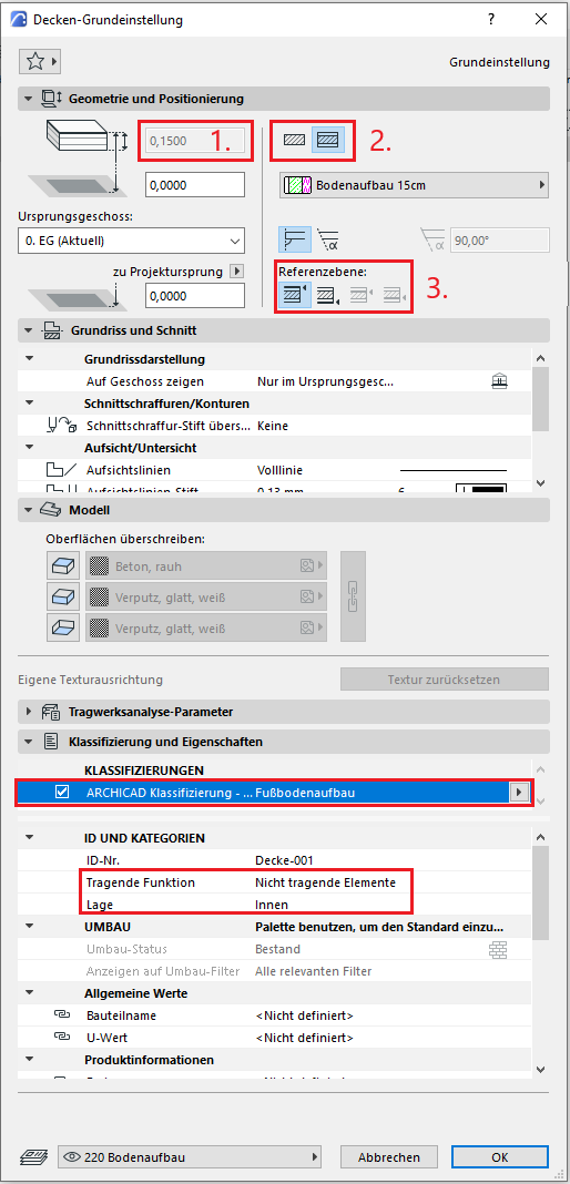
The first basic setting in geometry and positioning concerns the thickness of the slab. This can either be selected manually and assigned a building material, or it can be determined automatically by a multi-layer component.
The second default setting defines the structural method: Single-layer or Multi-layer. It is recommended that you always select the Multi-layer setting. The reason for this is that even at the very beginning of a project, during the study phase when building elements are represented in a simple (single-color) display, the multi-layer structure allows for very good control of the building element right from the start. On the one hand, this defines specific floor layouts (living areas, wet rooms, hallways, etc.), and on the other hand, it allows for a more precise definition of the floor in terms of its use right from the start.
Furthermore, this approach is highly recommended for saving time and optimizing a project: as soon as a structure catalog is available, these temporarily defined multi-layer components can be adjusted accordingly—floor structures that reference this multi-layer component immediately adopt this new structure.
Note: When modeling floors, a distinction is made between different types (according to ÖN A 6241-2, Appendix A): A floor slab is modeled as a single-layer component spanning the entire floor. The floor structure and the suspended ceiling, on the other hand, are modeled as multi-layer components, as these structural elements are room-specific. In addition, there are various modeling rules for the different structural elements.
The third default setting defines the position of the reference line. This is specified differently depending on the type of ceiling (floor slab, floor structure, underlayment, suspended ceiling):
Floor Construction
For the floor structure, the reference plane can be selected at the bottom. The lower edge thus lies at the floor level of the rough slab, and the structure extends upward as changes are made. A floor structure consists of all layers located above a floor slab. Under-slab insulation is also modeled as a separate multi-layer component and behaves like a suspended ceiling with respect to its reference line.
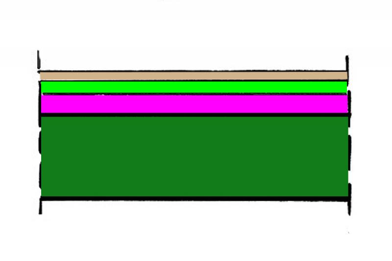
In this phase, the component is typically created (as a separate element independent of the raw floor slab). Colored floor plans are also often required.
Presentation
Cross-sectional view
visual distinction between the subfloor and the floor
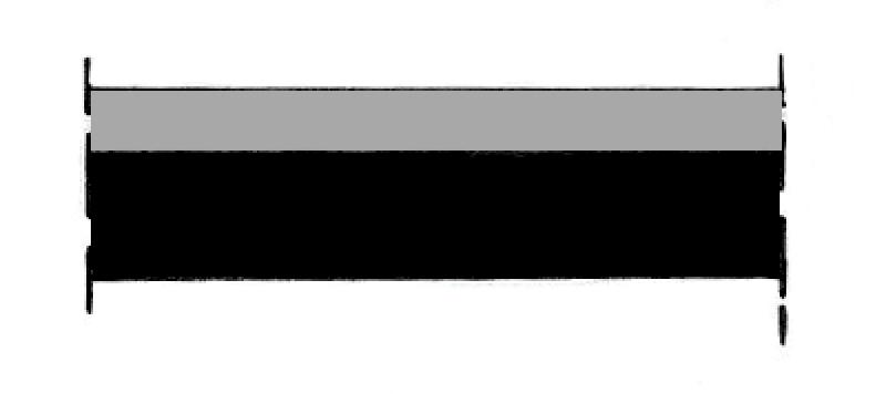
visual distinction between the subfloor and the floor
Features
Feature
- Fire compartment-defining element
- Fire resistance class
Parameters
- Tilt (top side)
Outline Information
Labeling
During this phase, the system is labeled.
Instructions
Create:
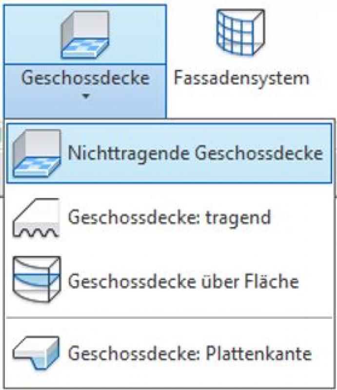
Floors are modeled using the command Floor Slab -> Non-Load-Bearing Floor Slab.
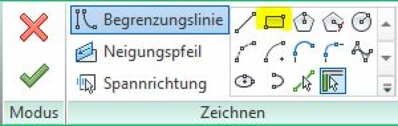
To do this, switch to the floor plan where the floor is to be created, and in Sketch Mode, under Draw, use the Boundary Line tool to create the floor on the load-bearing floor slab.
Now exit Sketch Mode by clicking the green checkmark. If necessary, assign the floor created in this way to the correct layer in the Properties window under "Dependencies." The best way to verify that the dependency has been set correctly is to check it in a section view.
Notes:
- Floors have their elevation reference point on the top surface. Depending on the location of the reference plane, a horizontal offset may be specified to ensure that the floor does not intersect with the rough ceiling.
- For raised floors, the air gap in the construction must be taken into account. If the air gap is missing or has the wrong thickness, this can otherwise result in incorrect elevations in the corresponding dimensions.
- If a system type designation is defined (e.g., FB01), the type number must also be included in the Revit type designation.

You can check the thickness of the air layer by going to Type Editing -> Design -> Edit, then selecting "Edit Assembly" in the window that opens, and checking the "Layer Thickness" field.
The basic modeling of a floor slab in ARCHICAD does not differ across the various design phases, nor does it differ from the modeling of other types of slabs.
The new features and parameters for this phase must be added in the appropriate sections of the component's settings dialog.
The description of the settings dialog and the corresponding procedure can be found in an earlier section of this article.
The labeling and dimensioning of the component should always be done associatively. Instructions on how to do this in ARCHICAD can be found in the relevant articles.
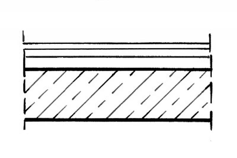
Presentation
Cut
visual distinction between the subfloor and the floor
visual distinction between the subfloor and the floor
Features
Feature
- Component activation
- Fire performance
- Sound insulation class
- Impact sound reduction index
- U-value
Parameters
- Gross ceiling area
- Net area of ceiling cladding
Outline Information
Labeling
The floor structure types are typically identified indirectly using the room codes for the corresponding rooms.
Instructions
Labeling is done indirectly using room stamps. To do this, the "Floor" parameter of the rooms is used and assigned a value such as "FB 02" or "Carpet." This parameter is read by a suitable room stamp and thus appears on the corresponding plan.
Since the value entered manually in the "Floor" room parameter is not automatically updated when the floor is modified later, you must verify that the value of the "Floor" room parameter matches the actual floor. This is usually done manually.
Instructions on how to create color-coded floor plans can be found in the articles "Areas and Zones" and "Color Scheme."
Gradient:
Slopes are not shown in cross-section; they are represented in the floor plan using 2D slope components.
Representation of slopes in cross-sections:
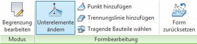
Modeling is performed via Shape Editing -> Modify Sub-elements (note that the floor must not have more than 4 edges, otherwise triangulation will occur). Additional cutouts are created using the Open feature. For layers with varying thicknesses, the "Variable" option is enabled in the Hooks settings.
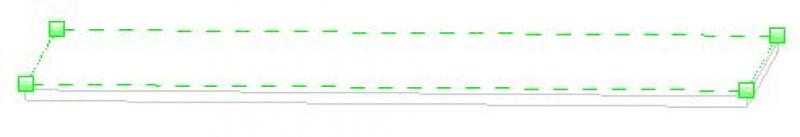
Procedure:
Mark the floor you want to edit, and select the "Modify Subelements" command in the toolbar.
In the 3D view, you can now see green boxes at each corner of the floor.
By checking the boxes, you can manually enter the desired angle of inclination.
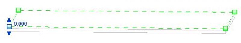
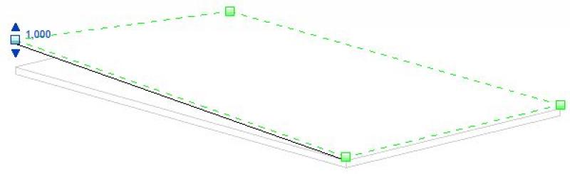
Alternatively, the elevation value for the slope can also be entered in the editing bar.

Note: If the altitude is too high, this may result in inaccuracies in the terrain model. In this case, a warning will appear.
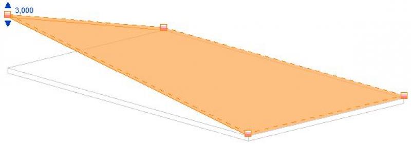
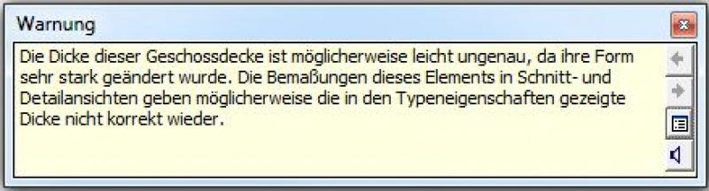
If this is the case, you can undo the entire process by selecting Form Editing > Reset Form.

The basic modeling of a floor slab in ARCHICAD does not differ across the various design phases, nor does it differ from the modeling of other types of slabs.
The new features and parameters for this phase must be added in the appropriate sections of the component's settings dialog.
The description of the settings dialog and the corresponding procedure can be found in an earlier section of this article.
The labeling and dimensioning of the component should always be done associatively. Instructions on how to do this in ARCHICAD can be found in the relevant articles.
Presentation
Cut
visual distinction between the subfloor and the floor
visual distinction between the subfloor and the floor
Presentation as a complete package

Features
Labeling
- Elevation marks in floor plans and sections
- Layer structure or system structure in the section
Instructions
Due to the wide variety of regulatory requirements, there is no one-size-fits-all solution for this phase. However, here are some general guidelines for improving quality and preventing errors:
- View templates should always be used for graphical customizations, rather than making individual adjustments to each drawing.
- For additional information in the drawing content, always use text families instead of plain text.
Color-coded overview plans are often created during this phase to illustrate the various floor structures in plan view; see floor plans for more information.
The structures are shown in greater detail in the close-up views.
Detailed design plans typically require so-called "floor plans," which differ significantly from general floor plans in that they contain more detailed information and are drawn to a smaller scale (for example, 1:50).
Presentation
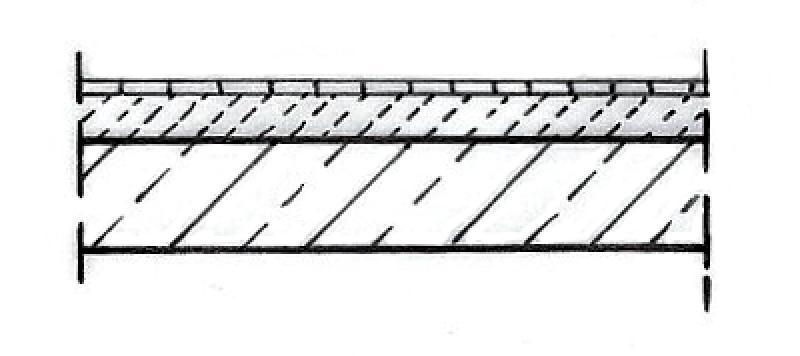
Cut
Model
Features
In this phase, the following geometric features are defined:
Feature
- Smoke emission class
- Reference
- Drip formation class
- HollowCorePlugging
- Precast concrete floor
Parameters
- Gross weight
- Net weight
- Thickness of the ceiling covering
Outline Information
Labeling
- Cross-sectional view of the layers
- Color-coded floor plans
- The floor plans are labeled using room codes
Instructions
Floor structures are defined using detailed cross-sections. This ensures consistency with the modeled floor.
The graphic can be customized using detailed elements. It is not necessary to provide detailed labels for each structure in building sections beyond the type designation.
The basic modeling of a floor slab in ARCHICAD does not differ across the various design phases, nor does it differ from the modeling of other types of slabs.
The new features and parameters added for this phase must be entered in the appropriate fields in the component's settings dialog.
The description of the settings dialog and the corresponding procedure can be found in an earlier section of this article.
The labeling and dimensioning of the component should always be done associatively. Instructions on how to do this in ARCHICAD can be found in the relevant articles.
To select flooring more quickly, you can temporarily enable "Select by area." The icon is located in the lower-right corner.

For floors with underfloor heating, it is recommended to set the layer containing the piping to "Core" in the multi-layer component so that the other floor layers are hidden in the "Without Finishing" structural view—this allows for more effective editing of this layer or handover to specialist designers.

Unfortunately, this content is available only to our Pro users.
If you'd like to read the full article, try the Pro account or become a Pro user.