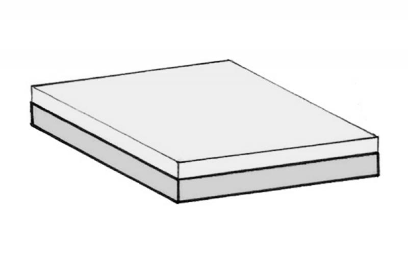
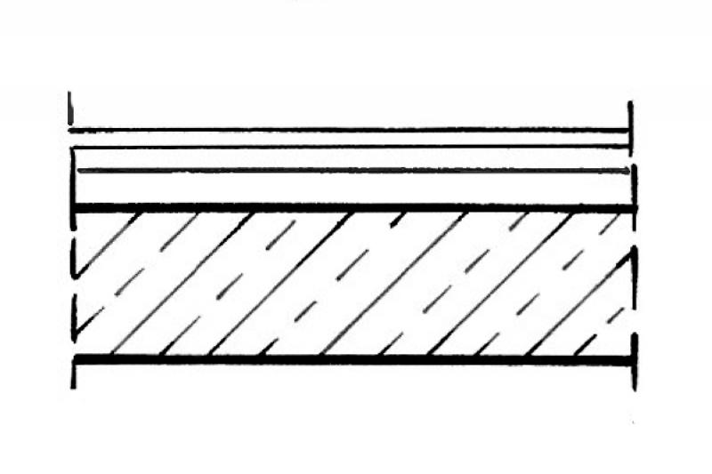
In this phase, floor slabs are modeled for the first time. It is not yet necessary to define materials (building materials).
Presentation
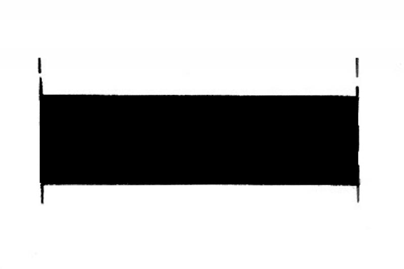
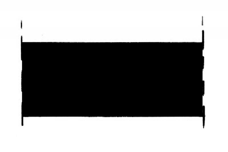
Cross-sectional view
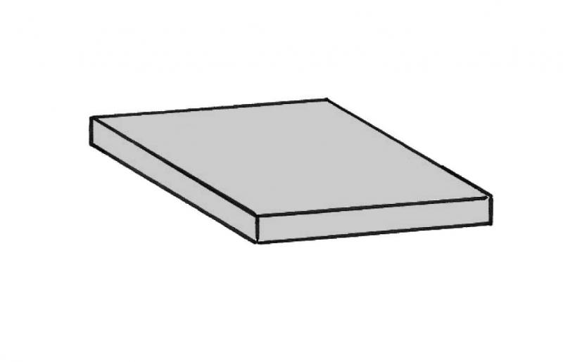
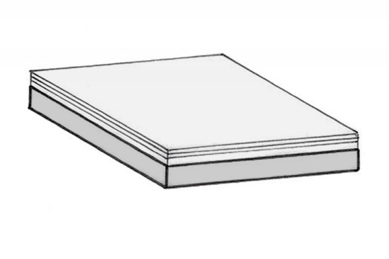
Model representation
Features
In this phase, the component is placed for the first time, thereby acquiring its geometric features.
Feature
- Status
- Supporting element
Parameters
- Gross area
- Gross volume
- Nominal ceiling thickness
- Net ceiling area
- Net volume
- Perimeter of ceiling
Outline Information
- Exterior element
- Room-enclosing element
Labeling
At this stage, the component is not yet labeled or dimensioned in the plan views.
Instructions
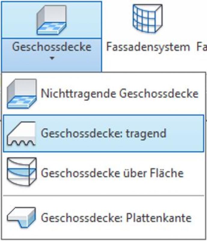
Floor slabs are modeled in Revit using the "Floor Slab: Load-Bearing" system family.
To model the floor slab, switch to the floor plan where you want to create it. Now use the Boundary Line drawing tool to model the desired shape of the slab. Exit Sketch Mode by clicking the green checkmark as usual.

Once a floor slab has been created, its shape can be modified later. To do this, select the slab and use the Edit Boundary command.

For more information, see Autodesk Help: Floor Slabs (General) and Creating a Floor Slab.
Ceiling openings
The following ceiling openings are also created using the Edit Boundary -> Ceiling Sketch Mode command.
- Mall Openings
- Cores
- Elevator shafts (Ü)
- Coves
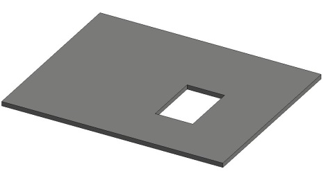
Breakthroughs
Instructions for creating cutouts can be found here.
The following elements are created as cutouts:
- Floor penetrations for building services components
- Installation openings
- Elevator shafts (Germany-Switzerland)
Room enclosure
The floor slab should be defined as an element that encloses the space.
Overview
The basic process of modeling a floor slab in ArchiCAD remains the same across the various design phases and is no different from modeling other types of slabs.
For ease of use in ArchiCAD, you can select the "Standard (Single Material)" setting.
For advanced users, it is recommended to always select the "Multi-layer" setting (or the "Complex Profile" for structurally more complex assemblies). The advantage of this is that even at the very beginning of a project, during the study phase when components are represented in a simple (single-color) view, the multi-layer structure allows for very precise control of the components from the start. On the one hand, this defines specific, recurring structural thicknesses; on the other hand, a more precise definition of the structural element regarding its use is established right from the start.
Sharing the data with, for example, structural engineers allows for early communication of the intended structural design. Furthermore, this approach is highly recommended for saving time and optimizing a project: as soon as a structure catalog is available, these temporarily defined multi-layer components can be adapted to match the structure catalog—construction elements that reference this multi-layer component immediately adopt this new structure.
For general information on how to use the Ceiling tool, please refer to the basic documentation provided by Graphisoft in the Help Center.
This documentation is based on the official template file 01 ARCHICAD 25 Template.tpl from the ArchiCAD 25 AUT version.
Building elements classified as ceilings or suspended ceilings are essentially space-defining—they are therefore defined as primary building elements or Building Element Class I, depending on whether they have a load-bearing or non-load-bearing function.
Note: Avoid using special settings (custom graphics, room area effects) within the default ceiling settings in order to provide other/subsequent project team members with a clear structure that minimizes the risk of errors.
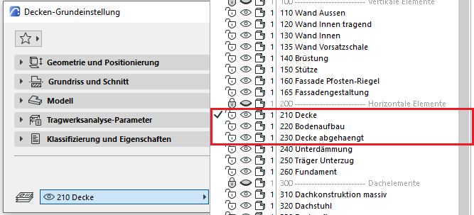
First, select the appropriate floor level for the ceiling. These are categorized as 210 (ceiling), 220 (floor structure), and 230 (suspended ceiling), based on their load-bearing structure or specific application:
Geometry and Positioning
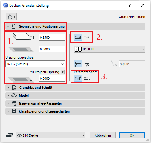
The first basic setting for geometry and positioning concerns the thickness of the slab. This can either be selected manually and assigned a building material, or it can be determined automatically by a multi-layer component.
The second default setting defines the structural method: Single-layer or Multi-layer. It is recommended that you always select the Multi-layer setting. The reason for this is that even at the very beginning of a project, during the study phase when building elements are represented in a simple (single-color) display, the multi-layer structure allows for very good control of the building element right from the start. On the one hand, this defines specific floor layouts (living areas, wet rooms, hallways, etc.), and on the other hand, it allows for a more precise definition of the floor regarding its use right from the start.
Furthermore, this approach is highly recommended for saving time and optimizing a project: as soon as a structure catalog is available, these temporarily defined multi-layer components can be adjusted accordingly—floor structures that reference this multi-layer component immediately adopt this new structure.
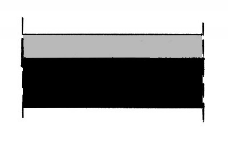
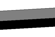
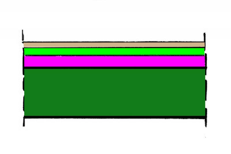
Note: When modeling floors, a distinction is made between different types (according to ÖN A 6241-2, Appendix A): A floor slab is modeled as a single-layer component spanning the entire floor. The floor structure and the suspended ceiling, on the other hand, are modeled as multi-layer components since these structural elements are room-specific. In addition, there are various modeling rules for the different structural elements.
The third default setting defines the position of the reference line. This is specified differently depending on the type of ceiling (floor slab, floor structure, underlayment, suspended ceiling):
floor slab
For floor slabs, the reference plane is taken at the top, since this aligns with the upper edge at floor level zero. A floor slab is also defined as a multi-layer component, even though it usually consists of only a single layer of building material. However, the multi-layer method allows for centralized control of floor slabs; furthermore, if an additional layer (e.g., a membrane) is required, it can be inserted into the MSB.
Instructions for positioning the reference line can be found here for suspended ceilings and for floor systems.
Floor plan and cross-section
Model data can also be displayed using projections in floor plans, elevations, and sections—the following description explains the available options.
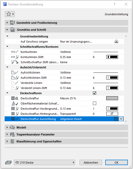
In the Floor Plan and Section section, the default setting for floor plan display is that the ceiling is shown only on the ground floor.
Section hatching and outlines should not be overridden in individual ceiling settings—these should always be configured centrally in the multi-layer component/building material to apply across all building elements, or the "Graphical Override Styles" option should be used for special/temporary display changes. For the ceiling, a ceiling hatch can be selected to be displayed in the floor plan.
Model
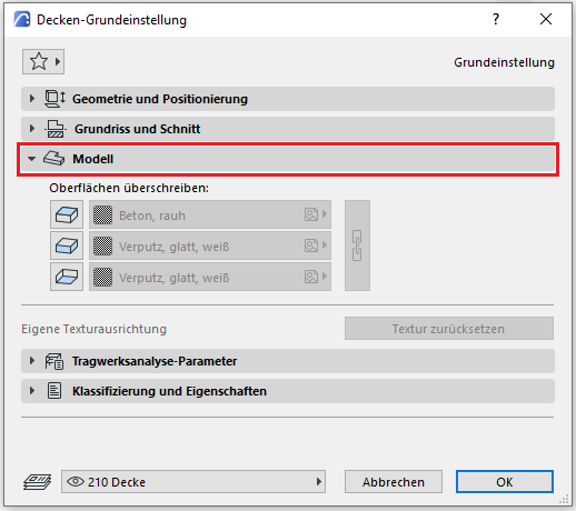
In the Model section, surfaces can be overridden manually or individually; however, to ensure a clear and consistent representation, the Graphic Override Styles option should be used for special or temporary cases.
Categories and Features
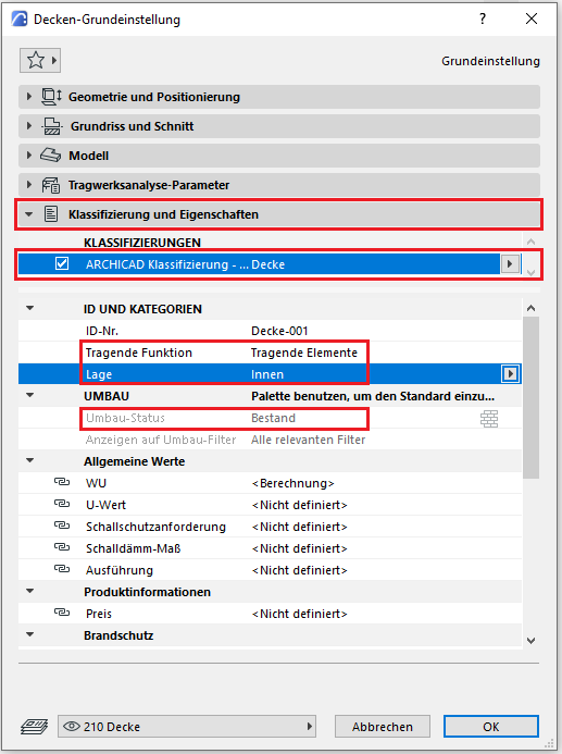
The element classification is the first definition in the Categories and Properties section—see also Classification. Selecting the "Ceiling" classification ensures that only the properties available for this classification according to IFC attributes are displayed in the lower field area. The “Ceiling” classification applies here to load-bearing ceilings; for floor structures and underlayments, the “Cladding/Flooring” classification is selected, and for suspended ceilings, the “Suspended Ceiling” classification.
The three properties that also serve a specific function within ArchiCAD are Load-Bearing, Location, and Renovation Status—these affect either the structural representation method, the envelope function (in other programs), or the renovation filter. All other attributes must be selected individually or determined in accordance with the project’s organizational guidelines (e.g., project manual or organizational manual).
Sloped floor slabs
If floor slabs are modeled with a slope, the Roof tool is used for this purpose. Care must be taken to ensure that the building elements modeled in this way are classified as a floor slab and not as a roof.
During this phase, the material (construction material) and the load-bearing capacity of the ceiling are defined. If it is foreseeable that the ceiling will have a slope, this does not necessarily have to be implemented in the model at this stage, but it should at least be noted in the 2D floor plan and section.
If it is clear that the rough slab conceals a utility layer or additional load-bearing elements such as joists beneath it, the architectural design may include a placeholder below it (see Conceptual Modeling).
Presentation
Cross-sectional view
Model representation
Features
Feature
- Fire compartment-defining element
- Fire resistance class
- Tilt (top side)
Labeling
In this phase, ceilings are generally not labeled or dimensioned in any projection plane. Only in the case of sloped ceilings may it be necessary to indicate the slope information in the floor plan and section.
Instructions
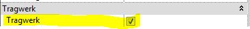
Structural floor slabs are load-bearing elements and should always be marked as "load-bearing" in the Properties window.
In this phase, the slope of the floor slabs is indicated solely by text using a 2D detail element.
The basic process of modeling a floor slab in ArchiCAD remains the same throughout the various design phases and is no different from modeling other types of slabs.
The new features and parameters added for this phase must be entered in the appropriate fields in the component's settings dialog.
The description of the settings dialog and the corresponding procedure can be found in an earlier section of this article.
The labeling and dimensioning of the component should always be done associatively. Instructions on how to do this in ArchiCAD can be found in the relevant articles.
During this phase of planning, the structural slab is supplemented with information from structural engineering and building physics. If necessary, the floor slab is given its slope in the model geometry. At the latest in this phase, any superstructures, such as floor slabs or suspended ceilings below, should be created as separate elements (see Hybrid Modeling).
Presentation
Cross-sectional view
Model representation
Features
Feature
- Component activation
- Fire performance
- Sound insulation class
- Impact sound reduction index
- U-value
Parameters
- Gross ceiling area
- Net area of ceiling cladding
Outline Information
Labeling
At this stage, the component is labeled only in the structural engineering drawings.
Load diagram: Load application
Layout plan: Position
Instructions
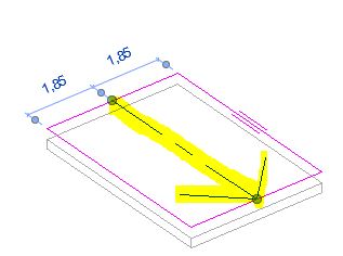
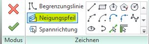
Dealing with slopes and inclines:
A one-sided slope of the floor slab is created using a slope arrow:
Floors with multiple slopes must be created using form editing:
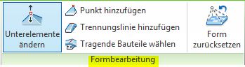
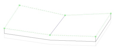
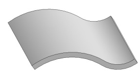
Create a project family of curved floor corners (non-analytical):
The basic process of modeling a floor slab in ArchiCAD remains the same across the various design phases and is no different from modeling other types of slabs.
The new features and parameters for this phase must be added in the appropriate sections of the component's settings dialog.
The description of the settings dialog and the corresponding procedure can be found in an earlier section of this article.
The labeling and dimensioning of the component should always be done associatively. Instructions on how to do this in ArchiCAD can be found in the relevant articles.
At this stage, at the latest, a distinction should be made between in-situ concrete floor slabs and precast floor slabs.
Presentation
This is where the different countries differ: In Austria, submission drawings are color-coded by building material; this classification is based on the reinforced concrete classification specified in the Vienna Building Code.
Cross-sectional view:
Features
Labeling
During this phase, the ceiling thickness must be labeled on the architectural drawings (elevation marks).
Instructions
To ensure that building materials are displayed in the correct colors in accordance with Austrian building codes, a color scheme that reflects the relevant state standards should be implemented.
The basic process of modeling a floor slab in ArchiCAD remains the same across the various design phases and is no different from modeling other types of slabs.
The new features and parameters added for this phase must be entered in the appropriate fields in the component's settings dialog.
The description of the settings dialog and the corresponding procedure can be found in an earlier section of this article.
The labeling and dimensioning of the component should always be done associatively. Instructions on how to do this in ArchiCAD can be found in the relevant articles.
During this phase, all information required for the bidding process (concrete grade, etc.) is added to the floor slabs. In addition, the component is reinforced. Depending on the collaboration scenario, this can be done either in 3D within the component or in 2D, decoupled from the model.
Presentation
Cross-sectional view
Model representation
Features
In this phase, the component is placed for the first time and automatically assigned geometric features.
Feature
- Smoke emission class
- Reference
- Drip formation class
- HollowCorePlugging
- Precast concrete floor
Parameters
- Gross weight
- Net weight
- Thickness of the ceiling covering
Outline Information
Labeling
During this phase, the floor slab is fully labeled and dimensioned. The leading edge of the slab, as well as the top and bottom edges of the slab in sections, must also be labeled.
Architectural Floor Plan:
- Bottom edge of the slab
- Top edge of the rough ceiling
Floor Plan and Structural Design:
- Bottom edge of the slab
- Top edge of the rough slab
- Ceiling thickness
- All information relevant to the shell construction
Instructions
The information regarding the reinforcement to be used in this phase must be provided by the structural engineering team and incorporated into the floor slab.
The basic process of modeling a floor slab in ArchiCAD remains the same throughout the various design phases and is no different from modeling other types of slabs.
The new features and parameters added for this phase must be entered in the appropriate fields in the component's settings dialog.
The description of the settings dialog and the corresponding procedure can be found in an earlier section of this article.
The labeling and dimensioning of the component should always be done associatively. Instructions on how to do this in ArchiCAD can be found in the relevant articles.

Unfortunately, this content is available only to our Pro users.
If you'd like to read the full article, try the Pro account or become a Pro user.