Area tools are often used in the early stages to visually highlight departments, zones, areas, or uses, for example. Areas are generally more expansive than individual rooms.
For example, they are used to calculate gross floor areas and represent them graphically. Rooms would be unsuitable for this purpose, as they only represent net floor areas.
For color schemes, room properties can be used to distinguish rooms from one another by color. For additional information, see also Autodesk Help: Color Schemes.
Presentation
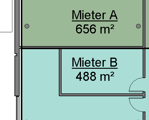
Plan view
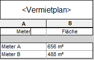
List view
Features
Features are defined according to the specific use case.
Once the report is generated, the following parameters are available as a minimum:
- Name
- Area
This method requires special floor plan views.
The article "Land Use Plan" describes how these are created and how to use them.
For more information on this topic, see the Autodesk Help article "Creating Floor Plans."
Features
Once the report is generated, the following parameters are available as a minimum:
- Area
- Perimeter
- Description
Instructions
First, open one of the floor plans mentioned earlier.
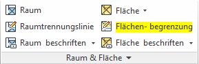
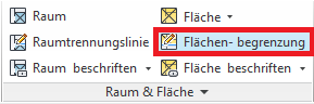
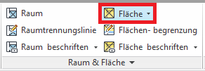
To create surfaces, you need surface boundary lines. These can be found under the Architecture > Space & Surface > Surface Boundary tab.
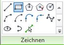
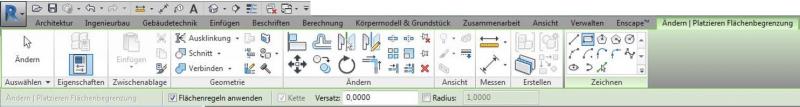
Clicking the button takes you to the Edit Mode: Change/Place Area Boundary. Select one of the drawing tools here and outline the desired areas.
If necessary, the area boundary line can be locked in place using the locks.
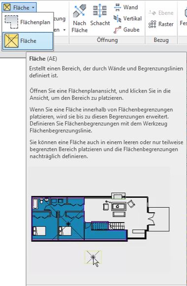
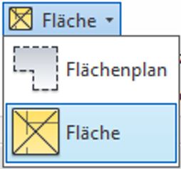
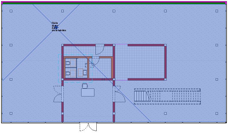
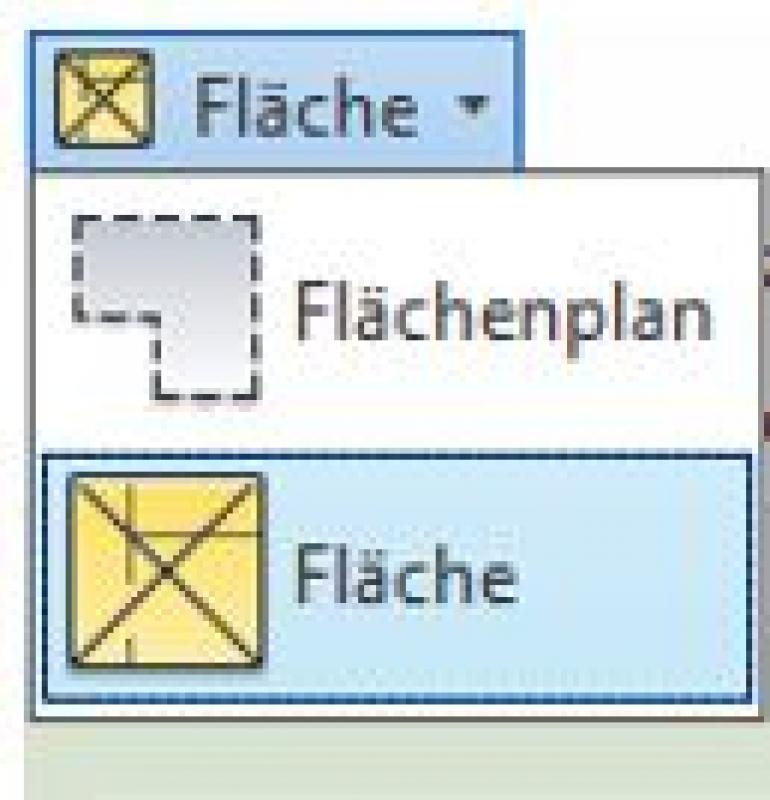
Once all the necessary area boundary lines have been drawn, you can begin placing areas. To do this, go to Architecture > Space & Area > Area and select the "Area" command from the drop-down menu.
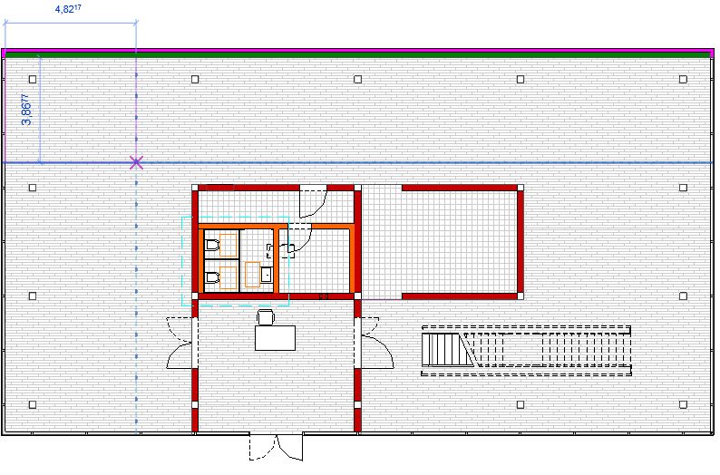
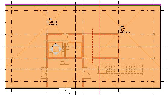
With the command enabled, you can now place the shapes within the previously drawn boundaries by moving the mouse over the desired area and simply clicking to place the shape.
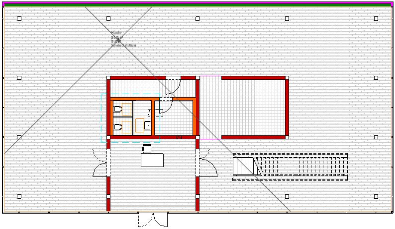
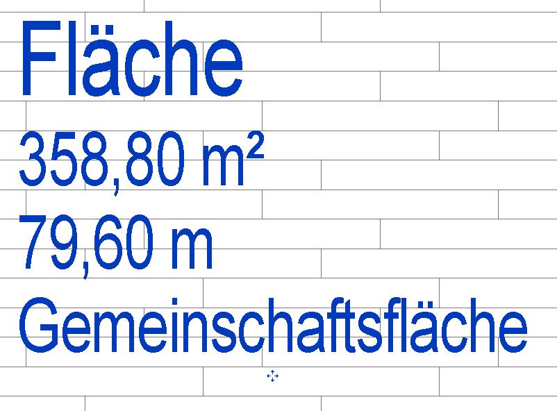
In the example shown
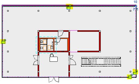
Once an area has been successfully placed, it is displayed in yellow.
This color highlighting remains in place until the area command is completed. This prevents two (different) areas from overlapping.
However, if a surface is accidentally placed twice or overlaps with another existing surface, Revit will display an error message and the affected surface will be highlighted in orange.
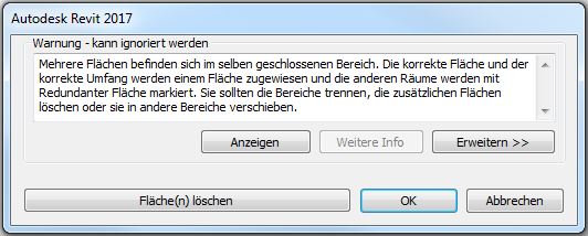
Clicking Cancel will end the current placement process. This will also remove the most recently placed surface from the model.
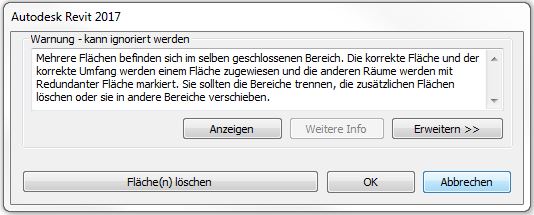
Clicking "Delete Area(s)" removes the most recently added or duplicate area from the plan, but it remains in the model.
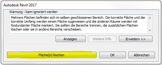
This is indicated by a Revit warning that pops up:
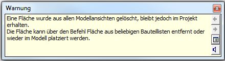
All surfaces in the model can be modified as desired or removed from the model entirely using the part lists.
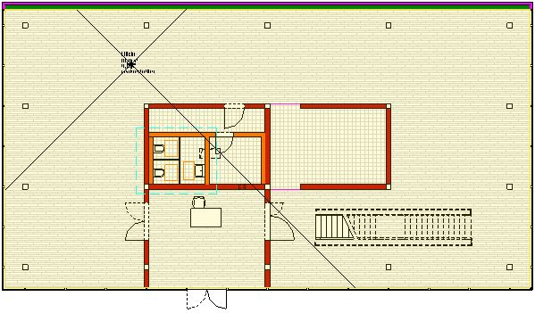
When you exit the Area command (Enter/Esc), the colored markings on the previously placed areas disappear. If you select the command again, the areas become visible once more.
Note:
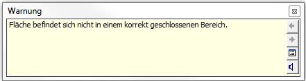
If a surface is accidentally placed outside a surface boundary, Revit displays a warning that the surface is not within a properly closed area.
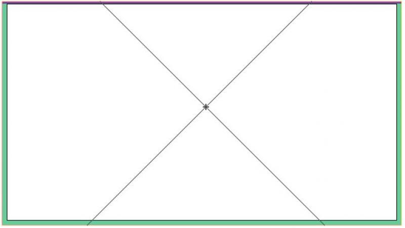
To edit a face, move the mouse over the face label. Use the Tab key to choose whether to select the face label or the face itself.
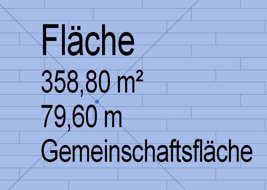
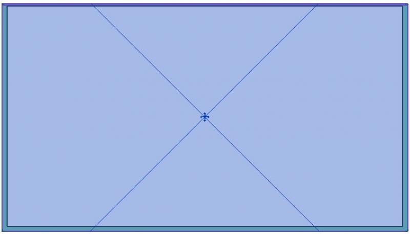
If the shape has been selected correctly, it will be highlighted in blue, and a cross will appear in the center to indicate the dimensions of the placed shape.
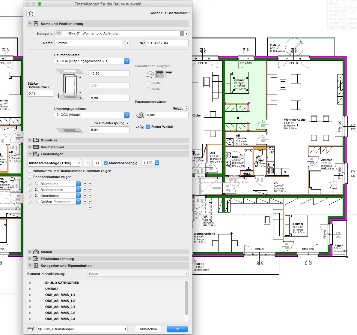
You can now edit the surface parameters in the Properties window. These include, for example, the following parameters:
- Editing area
- Number
- Name
- Area type
Parameter values such as area in square meters, perimeter, or height used for calculations are automatically retrieved and displayed in the Properties window. These values cannot be changed manually.
Net floor areas are calculated on a room-by-room basis.
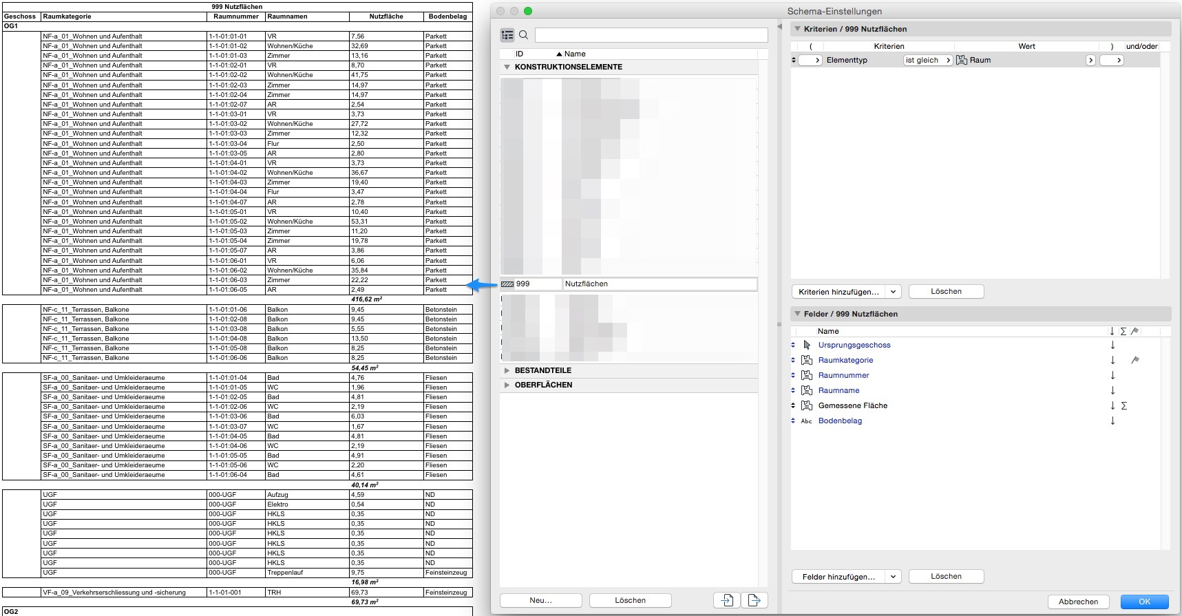
To analyze room areas, a default list is available under Reports > Elements > 000 Room Book; this list can be customized by the user.
Room categories provide a convenient way to manage room data. Furthermore, the ID, room number, and room name are all well-suited for logically grouping different rooms:
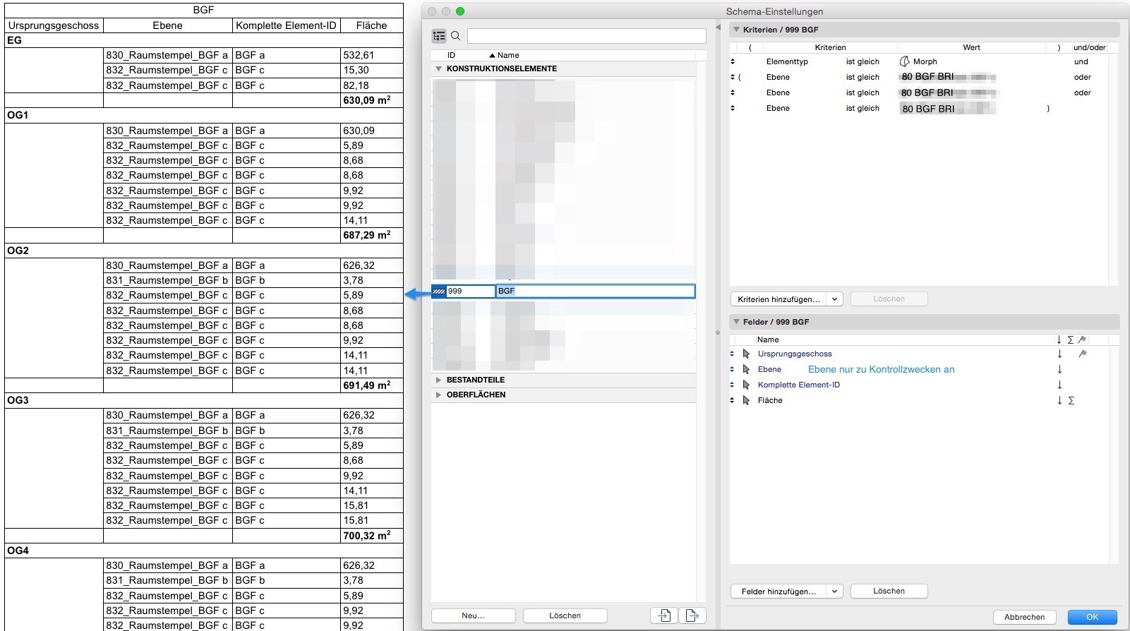
To determine the gross floor area, a contiguous area is defined within all enclosed room boundaries by creating a new floor plan. This new floor plan must be labeled accordingly.
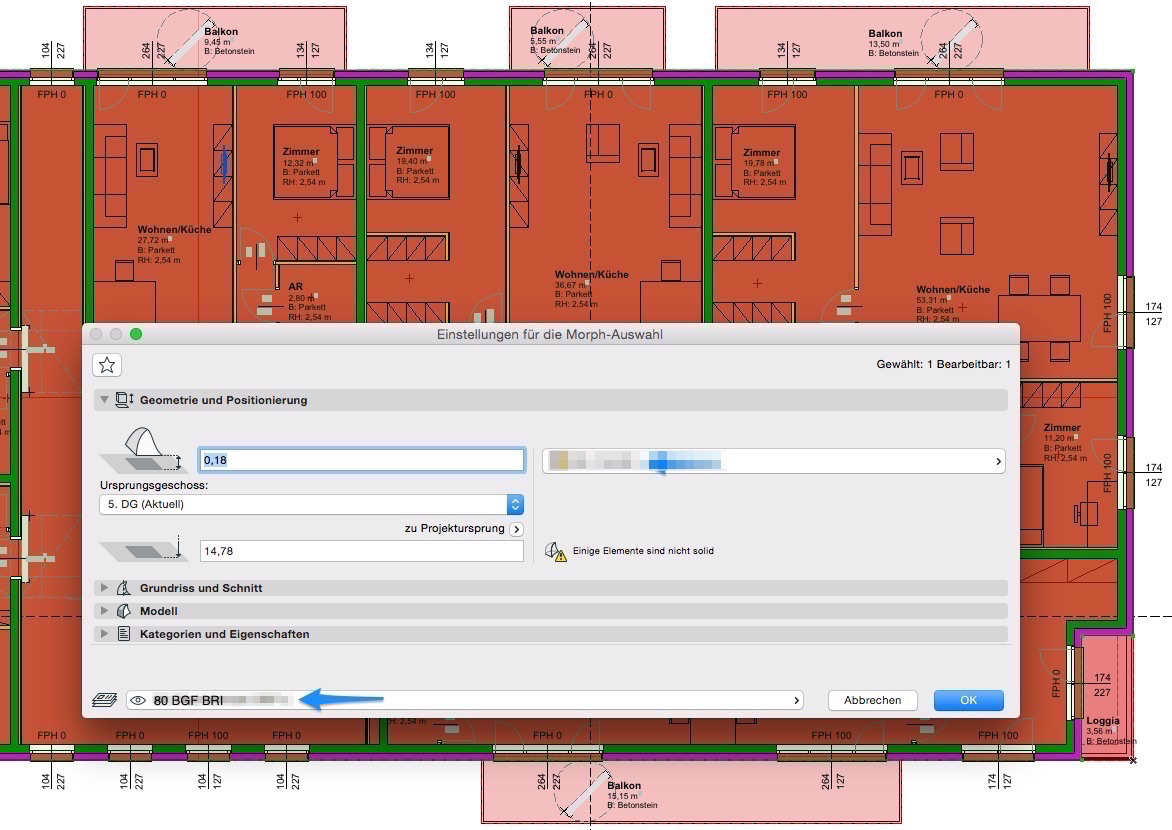
To calculate and evaluate the gross floor area (GFA), either hatches or morphs can be used. To be included in an IFC file, the areas should be created as morphs. These can be evaluated in the same way as hatches.
The gross floor area (GFA) can be defined as a Morph surface or as a Morph solid. Both methods can be used to calculate the GFA; the solid can also provide the building area (BA) at the same time—although the BA can also be calculated using the Morph floor area and floor height.
Independently defined areas
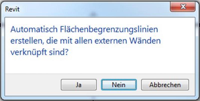
These are not associated with building components and are not linked to external walls during creation.
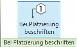
To do this, when creating the object, you must prevent the automatic creation of area boundary lines by clicking "No" in the pop-up window:
Use the "Area Boundary" button to define the desired areas.
The boundaries of the areas are defined using the drawing tools.

Then use the "Area" command to place the area(s).
If the shape has been successfully placed, this is indicated by an X in the selected area.
Rooms are generally defined in relation to the building elements surrounding them. If a room is not enclosed—or not fully enclosed—by building elements, a line created using the "Room Boundary" function can be used as an alternative.
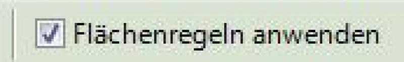
Manual placement—that is, placement without connections—is still possible (room boundaries in the building elements or room separation lines must be disabled); however, in this case, the room will no longer be automatically updated on command, and errors may occur in the area calculation.
Unlike hatching, you do not need to draw boundary lines twice when creating solid areas.
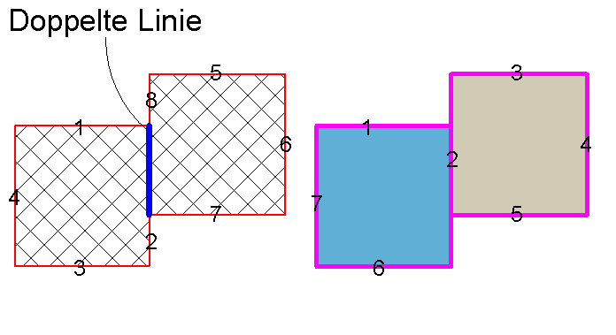
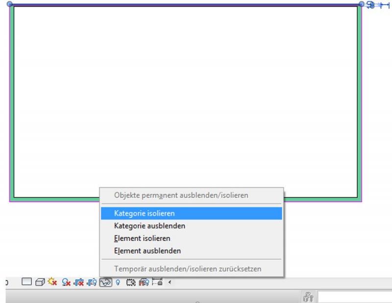
It is much easier to edit area boundaries if you first select a specific area boundary line using the Tab key and then temporarily isolate the category. You can do this either by using the IC (isolate category) shortcut or by clicking the magnifying glass icon on the toolbar at the bottom of the screen:
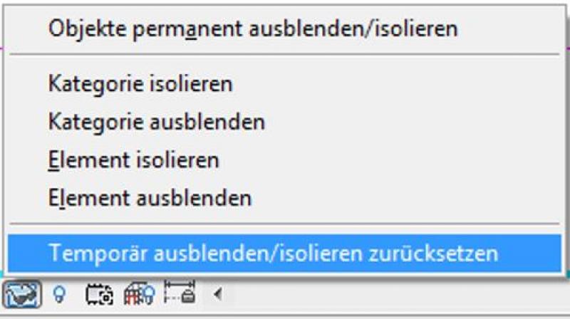
You can undo this hiding using the HR shortcut or by clicking the familiar icon again:

Unfortunately, this content is available only to our Pro users.
If you'd like to read the full article, try the Pro account or become a Pro user.