From a structural engineering perspective, a roof is defined as the horizontal spatial enclosure of a building’s vertical envelope. Due to their diversity and wide variety of construction methods, roofs represent a complex building element within the BIM workflow. Furthermore, different BIM programs vary significantly in the design of their tools for creating roof elements. Depending on the roof type, a combination of various basic elements may be used, such as floor slab elements for flat roofs or main and secondary beams in conjunction with roof elements for sloped industrial building roofs.
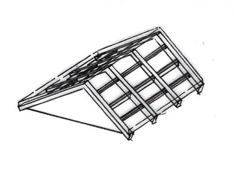
The term "roof" initially refers to the entire layered structure—from the roof covering as the topmost layer down to the bottom layer of the roof sheathing. Due to its complexity, the roof is viewed with increasing detail and modeled accordingly as planning progresses, moving from an initial abstraction in the model. This applies, for example, to structural elements such as purlins, rafters, or beams.
When discussing "roofs," special attention should be paid to the articles on "phase-based modeling" and "conceptual modeling."
Keywords: roofs, structure, system, attic, roof deck, waterproofing, roofing, roof covering, layer, slope
In this phase, roofs are modeled as abstracted entities to enable an efficient response to changes.
It is not yet necessary to define the materials.
Presentation
Plan view
Model representation
Features
Geometric features are automatically populated during the component modeling process.
Non-geometric features are added manually.
Feature
- Type of roof structure
- Status
Parameters
- Gross floor area
- Total thickness
- Net area
- Projected area
- Dormer width
- Dormer height
- Dormer type
Outline Information
- Exterior element
- Room-enclosing element
Labeling
At this stage, the component is not yet labeled in the plan views.
Instructions
Roofs are modeled in Revit using the Roof system family. Although roofs are typically non-load-bearing elements supported by surface structures and/or member structures, this distinction should not be taken into account at this stage.
Roofs can be modeled in three different ways.
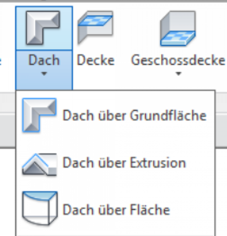
1. Modeling a roof over a base:
Similar to a floor slab, you first create a horizontal profile in sketch mode.
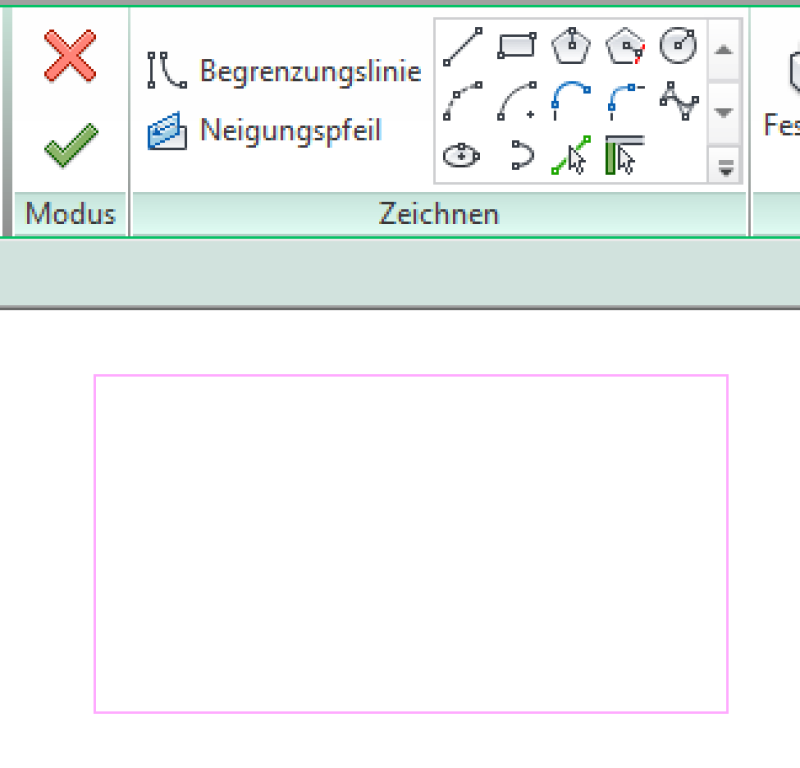
To model the roof, switch to the floor plan where you want to create it. Now use the Boundary Line drawing tool to model the desired shape of the roof. Exit Sketch Mode by clicking the green checkmark as usual.
For more information, see the Autodesk Help section on creating a roof over a floor plan.
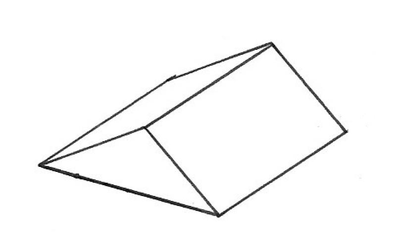
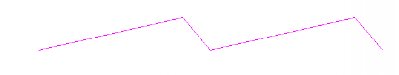
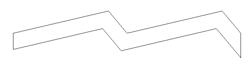
2. Creating a roof using extrusion:
Unlike when creating a roof over a base area, here a line is drawn in cross-section—that is, a vertical profile.
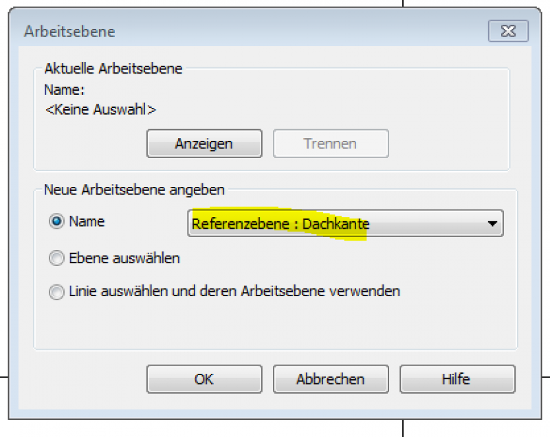
To begin modeling, switch to the section view where the roof will be created. The first step is to define the desired working plane. It is recommended to use a reference plane that forms one of the side edges.
Use the drawing tool to model the desired shape of the roof, and then exit sketch mode by clicking the green checkmark as usual.
The thickness of the roof is now extruded downward along the sketched line. The height of the roof depends on the position of the sketch in the view.
Note: The reference plane must be known; otherwise, it cannot be selected when assigning the reference plane.
For more information, see the Autodesk Help section on creating a roof using extrusion.
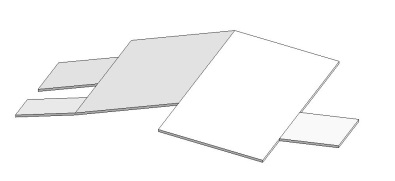
3. Creating a roof over a surface:
The "Roof over Surface" creation option requires a component or a solid on whose surface the roof is to be created.
For more information, see the Autodesk Help section on creating a roof from surface solids.
In this phase, the roof's construction type is determined by the material.
The modeling of flat roof slopes and roof pitches is not necessarily included in this phase, but should be added in two dimensions to the floor plan and section.
See also the article on insulation: Sloped-roof insulation
Presentation
Plan view
Model representation
Features
- Roof accessibility
- Fire resistance class
Parameters
- Roof pitch
- Volume
Outline Information
Labeling
It is not yet necessary to label roofs at this stage. However, general slope information and elevation data may be important in floor plans and sections.
Instructions
Dealing with slopes and inclines:
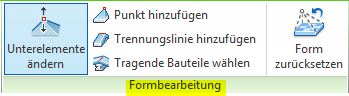
To change the shape of a roof, you can use the Shape Editing command to edit the surface of flat roofs. It is recommended that you first divide the entire surface into individual "panels."
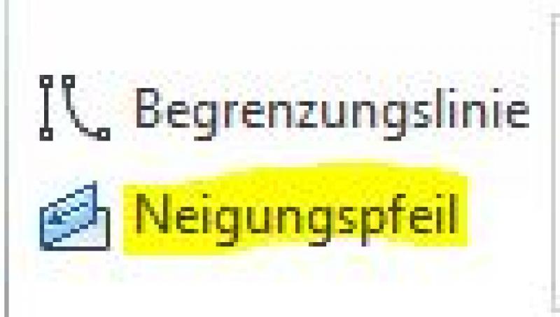
To create a single-slope roof, use the slope arrow in Sketch Mode to set the desired slope.
For more information, see the Autodesk Help section on creating a slope.
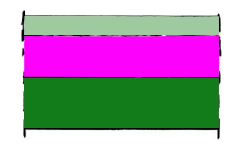
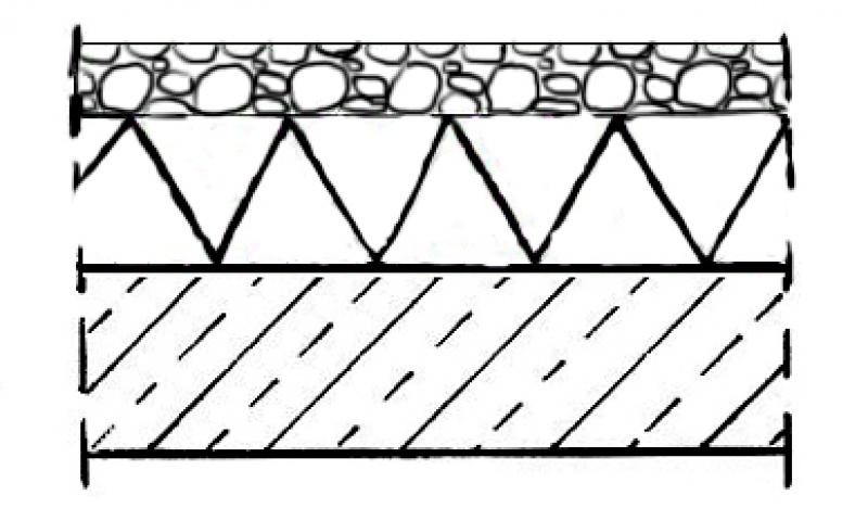
In this phase, the components of a roof are represented using hybrid or single-layer modeling; for more information, see "Multi-layer components."
For example, the main structural framework is expanded and the roof covering is defined.
Flat roofs are also given three-dimensional slopes and inclines.
Presentation
Plan view

Model representation
Features
- Sound insulation class
- U-value
Outline Information
Labeling
In the field of structural engineering, the following characteristics are labeled.
Load diagram: Load application
Layout plan: Position
Instructions
The template already includes roofs that can either be used as is or serve as a basis for new roof types. The roof type designation provides information about the material and thickness. Relevant additional information can be added at the end.
When making changes or additions, existing types should be duplicated, named appropriately, and not overwritten.
Care should be taken to ensure a consistent naming convention.
The parameters required for load and position plans are defined by the structural engineering design.
Presentation
The representation varies by country.
Cross-section:

Features
No attributes are added during this phase.
Labeling
Due to widely varying regulatory requirements, there is no one-size-fits-all solution for this phase. However, there are general guidelines for improving quality and preventing errors:
- For graphical customizations, you should always use view templates instead of making individual adjustments for each drawing.
- For additional information in the drawing content, always use text families instead of plain text.
Instructions
Structural and fire safety characteristics are usually incorporated into the model by the architectural design.
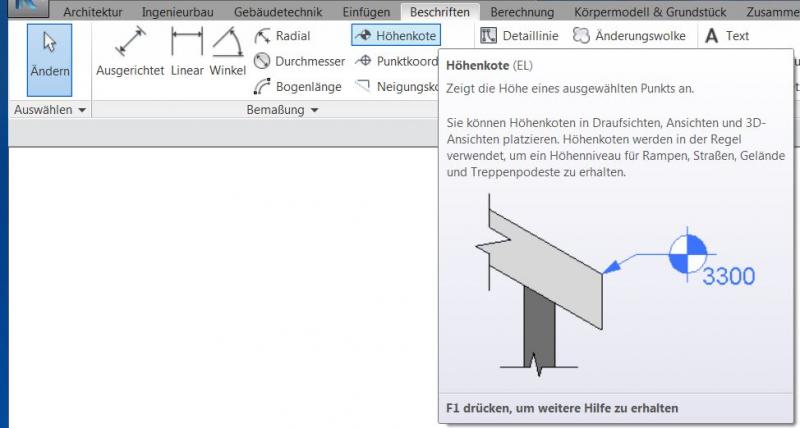
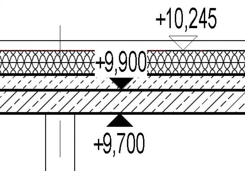
The "Elevation" command is available for labeling elevations, such as the top and bottom edges of a roof structure.
Example:
During this phase, all information required for the award of the contract and the execution of the construction work is finalized.
Presentation
Plan view
Model representation
Features
- Reference
Parameters
Outline Information
Labeling
During this phase, the roof is fully labeled, including details such as the roof structure, additional elevation data, relevant information regarding minimum clearances that must be maintained, and additional elevation data in sections.
Instructions
During this phase, the structural framework is completed, and all relevant connection details are worked out. We would also like to refer you to the following articles:
When creating labels, you should not use text at this stage either; instead, you should always use label families that read parameters.

Unfortunately, this content is available only to our Pro users.
If you'd like to read the full article, try the Pro account or become a Pro user.