Sloped insulation on flat roofs uses wedge-shaped insulation panels to direct water flow toward drainage elements.
When modeling sloped insulation and roof structures in general, special attention must be paid to modeling in accordance with the construction phase. Due to geometric complexity, various intersections, and dependencies with adjacent components, an excessive level of detail in early phases inevitably leads to time-consuming but avoidable revisions.
This article describes strategies optimized for modeling slope insulation in various authoring software programs.
Modeling is not yet necessary at this stage.
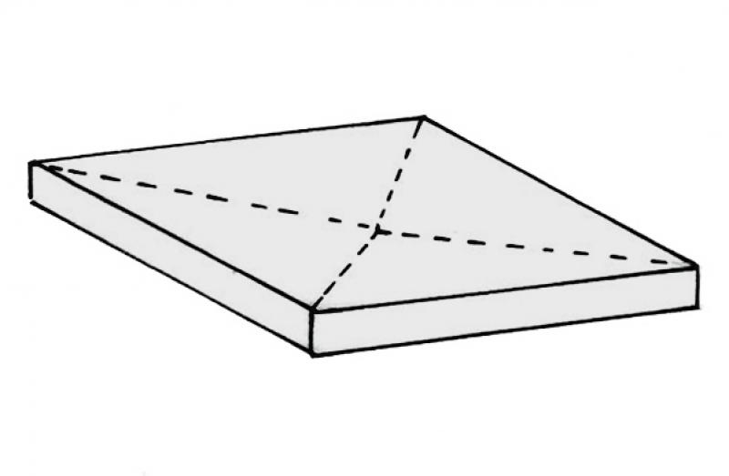
In this phase, the object is created.
The slope profiles of flat roofs, for example, with their folds on the upper surface, are not taken into account in this phase. The insulation for these roofs is given a uniform thickness in this phase.
Presentation
Cross-sectional view
Model representation
Features
Feature
- Type of roof structure
- Roof accessibility
- Fire resistance class
- Status
Parameters
- Gross floor area
- Total thickness
- Net area
- Projected area
Outline Information
- Exterior element
- Room-enclosing element
Labeling
At this stage, the component is not yet labeled in the plan views.
Instructions
In general, sloped roof insulation can be installed using either the roof system family or the floor slab system family. However, we strongly recommend using the roof system family.
A key advantage of this family is the reference plane on the bottom. This means that the component is built up from the bottom. This advantage will be particularly appreciated as soon as the component needs to be adjusted in height during further planning or, for example, retrofitted with a slope.
Modeling the slope and gradient is not yet necessary at this stage for flat roofs or floor slabs with a slight slope that are to be insulated. (This applies, for example, to outdoor garages and parking lots.) If a graphical representation is nevertheless desired, this information must be provided in a 2-dimensional floor plan.
The slope insulation should be at the same level as the corresponding structural floor slab or roof. This is possible because roofs are constructed upward and floor slabs are constructed downward.
Sloped roof insulation, made easy
In the early stages, slope insulation can be modeled and visualized using the Open Area tool. When doing so, ensure that the Open Area structure is set to "Solid Body" and that the open area is classified as a roof.
For general information on how to use the Open Space tool, please refer to the basic documentation provided by Graphisoft in the Help Center.
Geometrically Correct Construction of a Flat Roof
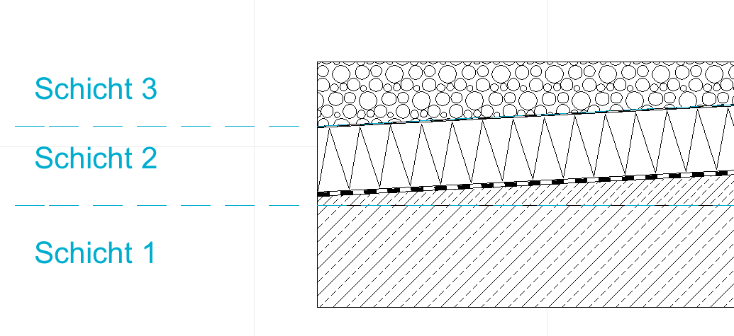
A geometrically accurate flat roof (with a low slope) is created using the roof and ceiling tools. It consists of three different components to ensure a geometrically accurate model:
- Layer 3: Roof structure finish
- Layer 2: Sloped roof (including slope insulation)
- Layer 1: Support structure
These are created as follows and then intersected using solid element commands:
Step 1: Create Layer 1 = Load-bearing structure = Floor tool with the reinforced concrete floor structure
Step 2: Create Layer 2 = Sloped Roof = Use the Roof tool to construct the sloped portion of the roof (depending on the roof type, this begins with, for example, the sloped concrete or sloped insulation)
Step 3: Align all sloped roofs in Layer 2 so that there are no gaps at the adjoining edges of the roofs—make sure that the minimum slope of each individual roof is not exceeded.
Step 4: Solid Element command: Select "Load-bearing floor" as the operator and "Sloped roofs" as the target elements, then execute the command with downward extension.
Step 5: Create the roof finish for Layer 3 = Use the Roof tool with the appropriate roof structure (e.g., gravel or extensive green roof)
Step 6: Solid Element command: Select "Sloped Roofs" as the operator and "Roof Structure Layer 3" as the target elements, then execute the command with downward extension.
During this phase of planning, all slope insulation is designed with geometrically accurate dimensions, including flat roofs and floor slabs with a slight slope.
Presentation
Cross-sectional view
Model representation
Features
- Sound insulation class
- U-value
Outline Information
Labeling
At this stage, it is not yet necessary to label the component.
Instructions
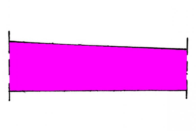
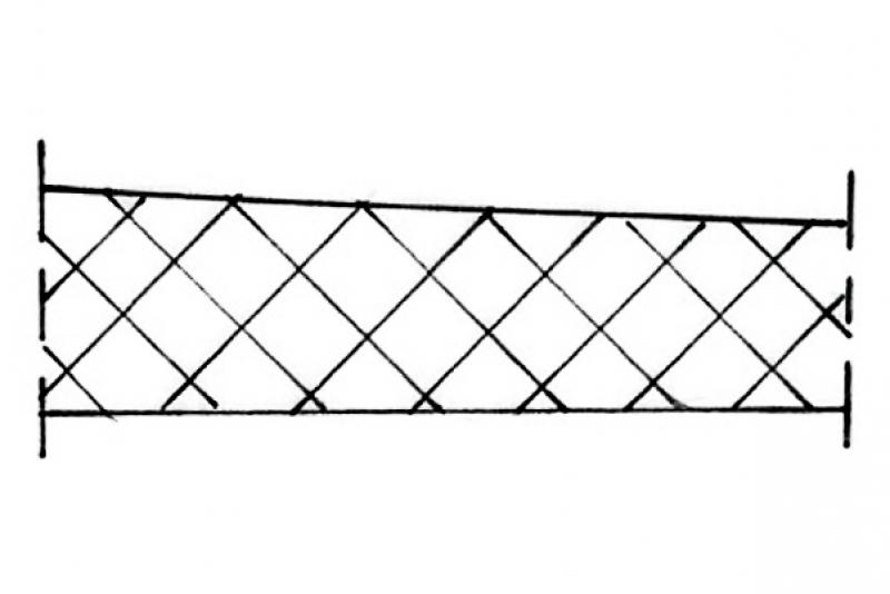
In this phase, the component must be represented geometrically correctly.
This means that the structures are given a three-dimensional slope, even in the case of flat roofs.
This requires types with variable layer thickness.
This can be easily verified by examining the design properties of the type.
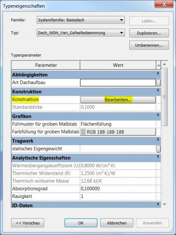
Clicking "Edit" opens the "Edit Component Group" menu
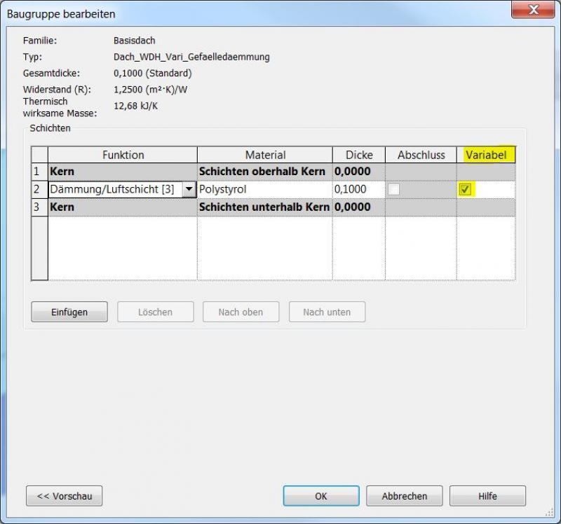
If a checkbox is selected in the "Variable" column, the height of an object's top edge can be adjusted while keeping the bottom edge at the same horizontal level, regardless of the specified layer thickness. "Variable" therefore refers to the layer thickness.
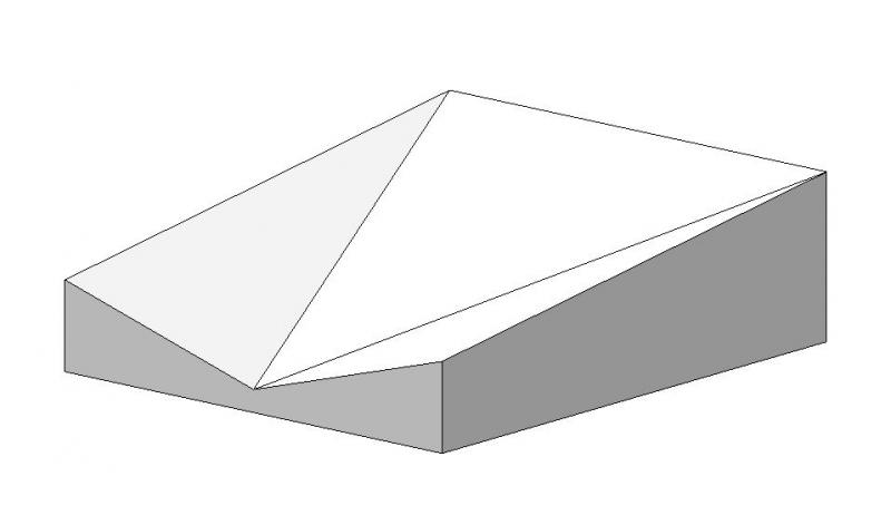
Example involving variability:
When the top edge is moved, the bottom edge remains horizontal.
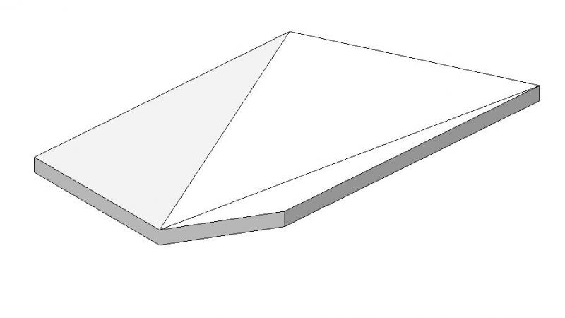
Example without variability:
When the top edge is moved, the bottom edge remains parallel to the top edge.
The "Slope Arrow" feature for creating slopes cannot be used with objects that have variability!
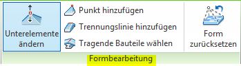
Form editing:
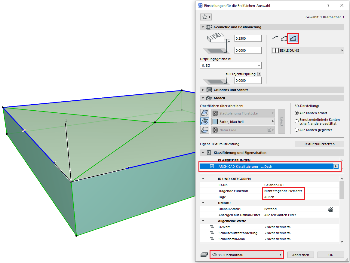
Once the correct type has been selected, you can begin modeling the surface.
This is done using the Form Editing command.
Selecting the object will display the menu.
The basic process for modeling sloped insulation in ARCHICAD remains the same throughout the various design phases.
The new features and parameters added for this phase must be entered in the appropriate fields of the component's settings dialog.
The description of the settings dialog and the corresponding procedure can be found in an earlier section of this article.
The labeling and dimensioning of the component should always be done associatively. Instructions on how to do this in ARCHICAD can be found in the relevant articles.
During this phase of planning, information regarding building physics and fire safety is incorporated into the design. Building code requirements must be taken into account.
Presentation
Cross-sectional view
Features
Labeling
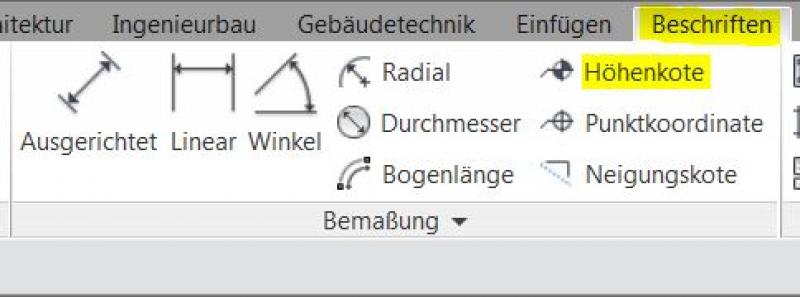
In this phase, the roof structure height is labeled. Elevation marks for the top and bottom edges are added.
Instructions
The building physics properties are assigned to the objects.
Most building physics properties will likely be type-specific. These should be added to the type parameters. All other properties are assigned to the instance parameters.
If only a few objects are affected, you can assign the instance parameters in the Properties window. If there are multiple objects, it may be helpful to make the additions in a part list.
The elevation marks are located under "Labeling"
The basic process for modeling a slope insulation in ARCHICAD remains the same across the various design phases.
The new features and parameters added for this phase must be entered in the appropriate fields in the component's settings dialog.
The description of the settings dialog and the corresponding procedure can be found in an earlier section of this article.
The labeling and dimensioning of the component should always be done associatively. Instructions on how to do this in ARCHICAD can be found in the relevant articles.
During this phase, all information relevant to the tender is added to the component.
Presentation
Cross-sectional view
Model representation
Features
- Reference
Parameters
Outline Information
Labeling
Newly created views that are used to generate plans must, of course, be relabeled. Existing views should already be adequately labeled.
Instructions
There are no specific requirements. The general workflow from the previous phases should be followed here.

Unfortunately, this content is available only to our Pro users.
If you'd like to read the full article, try the Pro account or become a Pro user.