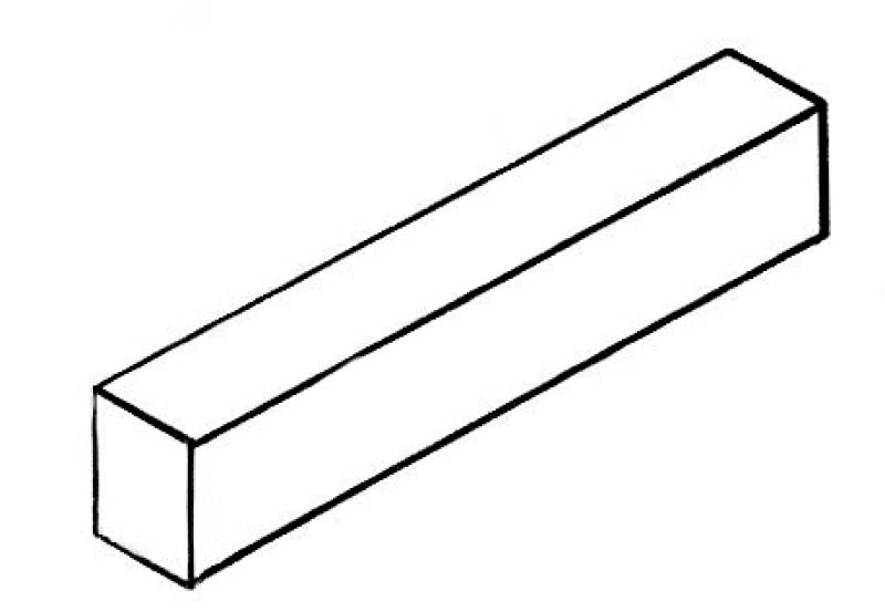
"A beam is a structure that typically runs horizontally, is narrower and slimmer in relation to its length, and transfers the loads resting on it to walls or vertical supports. Unlike an arch, a beam is primarily subjected to bending loads. Materials with high tensile strength, such as wood, metal, or reinforced concrete, are required."
Source: Wikipedia
In BIM workflows, beams are modeled using dedicated tools across different software platforms. Joists are a special type of beam; although they are directly connected to a floor slab, they are typically modeled using the same tool. Another special type of beam is the truss beam; its modeling is described in a separate article.
Like all load-bearing components of a building, beams serve as an interface between architecture and structural engineering. If a model-based data transfer to structural analysis software is planned, it may be necessary to use specific modeling methods tailored to the particular software configuration during the modeling process. In particular, precast beams with their various notches present a special application scenario in which the requirements of the specific software configuration should be coordinated early on between structural engineering and architecture.
Search terms: Traeger, Trager, Treger, UZ, beam
In this phase, the main structural members of the structural system ("primary structures") are modeled for the first time. It is not yet necessary to define materials (building materials).
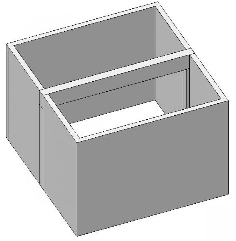
Beams are generally not modeled at this stage; alternatively, a reinforced floor slab can be created to represent the bottom edge of the structural element or the clear room height in place of the beam (the graphical requirements should be met in any case; see also Conceptual Modeling)
Presentation

Plan view (cross-section)
Model representation
Features
Feature
- Status
- Supporting element
Parameters
- Wide straps
- Gross volume of beams
- Total surface area of the beam
- Base area of the beam
- Beam height
- Tilt angle
- Beam length
- Beam lateral surface area
- Beam slope
- Net surface area of beam
- Net volume of girder
- Cross-sectional area of beam
- Lateral area of beam
Outline Information
- External element
Labeling
In this phase, a beam is not yet labeled in plan views.
Instructions
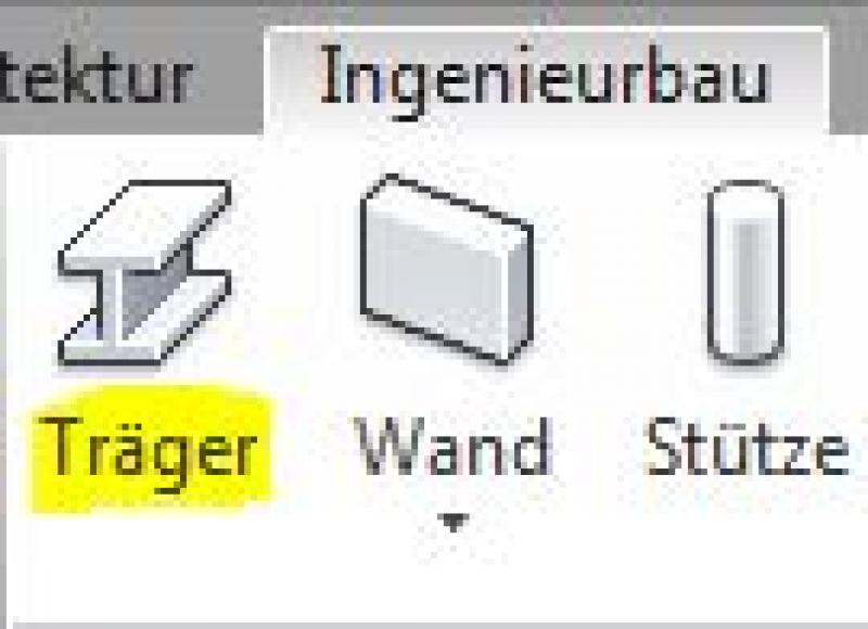
In Revit, beams fall under the Structural category and are created using the command >Civil Engineering > Beam. Beams are generally load-bearing components. Since they do not belong to the system families but rather to the so-called external (i.e., "loadable") families, they must be loaded from Revit Content as needed. Command:
The following special modeling considerations must also be taken into account for beams:
- Beams are generally modeled as load-bearing (the structural functions are automatically activated when the command is executed)
Support for beam:
When modeling in-situ concrete beams, care must be taken to ensure that the start and end points are always constrained by load-bearing elements—such as the center of a column or the axis of a load-bearing wall—to ensure that the beam is structurally sound in terms of structural analysis.
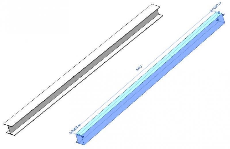
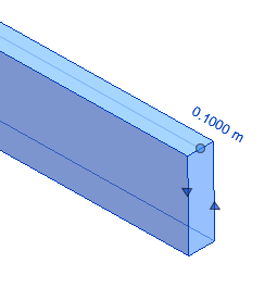
Inclined beams:
You can use the "Start Level Offset" and "End Level Offset" parameters to tilt a beam, for example, to match the slope of a sloped roof structure. These settings can also be adjusted directly on the beam in the modeling area: When a beam is selected, blue circles—known as shape handles—appear at the start and end points, along with input fields where a height offset can be specified.
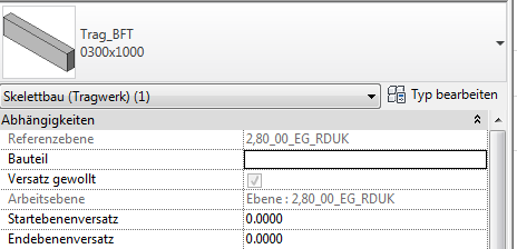
- Start plane offset: Specifies the elevation offset of the start point relative to the reference plane.
- End plane offset: Specifies the elevation offset of the end point relative to the reference plane.
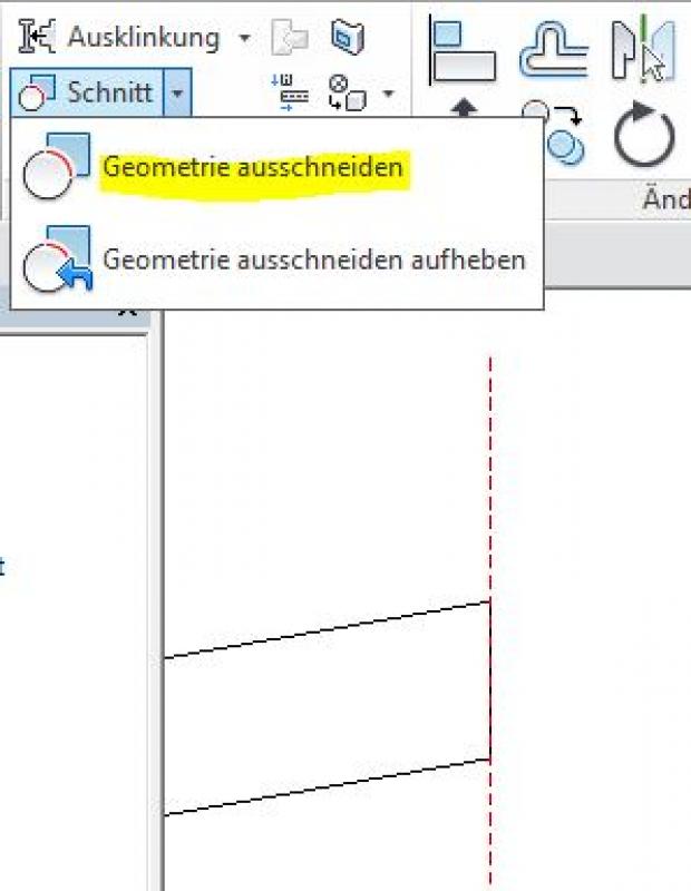
Angled beam ends:
The following methods can be used to cut the ends of a support at an angle:
- Create a reference plane that represents the section plane (this is typically done in a section; see the image below)
- Use the command >Modify >Section >Cut Geometry to "cut off" the beam at the reference plane (first select the beam, then the reference plane)
Important additional note regarding diagonally cut strap ends:
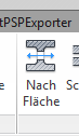
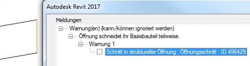
A member should not be trimmed using the command >Architecture >Opening >By Area, because this triggers a warning that, although it can be ignored, is saved along with the project file. As the project progresses, this can lead, on the one hand, to a significant deterioration in model performance if the number of warnings is high, and, on the other hand, to the inability to perform an IFC export required by external designers or clients.
Therefore, this approach should be avoided:
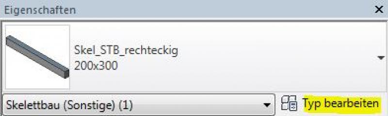
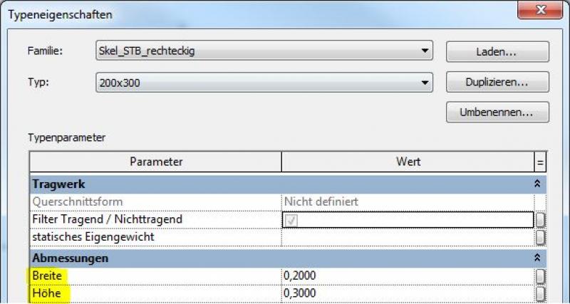
Additional beam cross-sections:
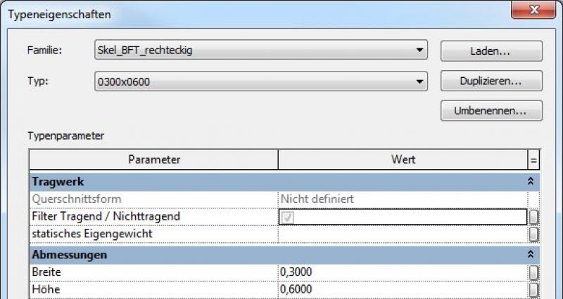
If you need an additional beam cross-section that is not yet included in the family, you should create a new type using the >Edit Type and >Duplicate commands. When creating a new beam type, be sure to give it a meaningful name.
New host families:
New carrier families can be created using the following family templates:
- Joists: >M_Structural Framing (joists and struts)
- Beams in general: >M_Skeleton Construction
Additional notes:
With 3D snap, the beam can be snapped to other structural elements in certain views. For example, if 3D snap is enabled, the roof beams will snap to the top ends of columns regardless of their height.
To specify the exact length of a line segment when sketching, click on the starting point and drag the mouse pointer in the desired direction. Enter the desired length and press the Enter key to place the line segment.
Reference level or reference height:
Ceiling beams and cast-in-place concrete joists are modeled on the same reference plane as the cast-in-place concrete slabs, i.e., the plane of the top edge of the slab (RDOK). It is important to note this, as the structural reference height of the beam is relevant, not just the portion of the beam that appears below the ceiling.
Steel beams, precast concrete joists, or similar elements that support a floor slab are modeled at the level of the bottom edge of the rough floor (RDUK).
During this phase, the structural engineering team determines the load-bearing capacity of the beams and, based on that, selects a material (construction material).
Presentation
Plan view (cross-section)
Model representation
Features
Labeling
In this phase, members are not yet labeled in plan views.
Instructions

Material assignment:
For carriers, material allocation is a two-step process:
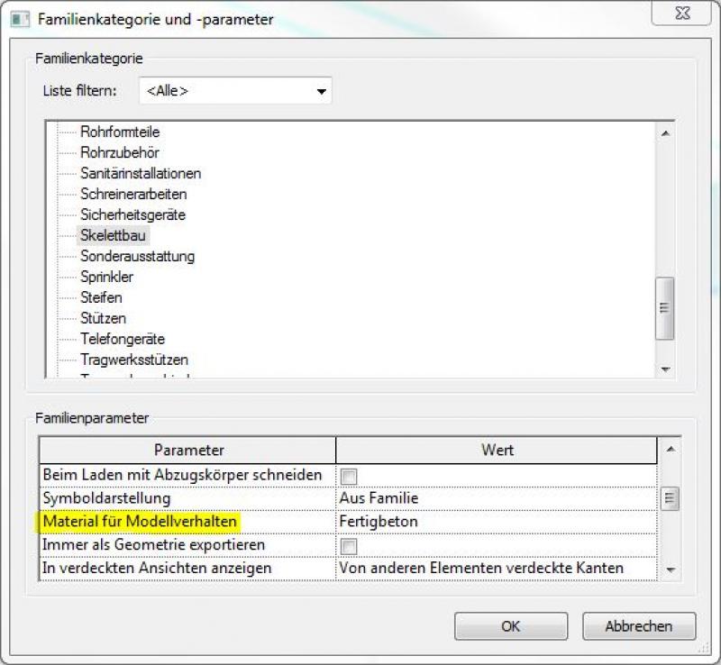
- Material assignment for structural analysis: This is done by selecting the family parameter >Material for model behavior in the family (using a precast concrete beam as an example):
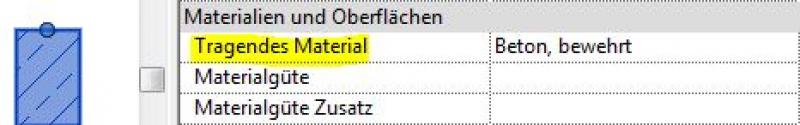
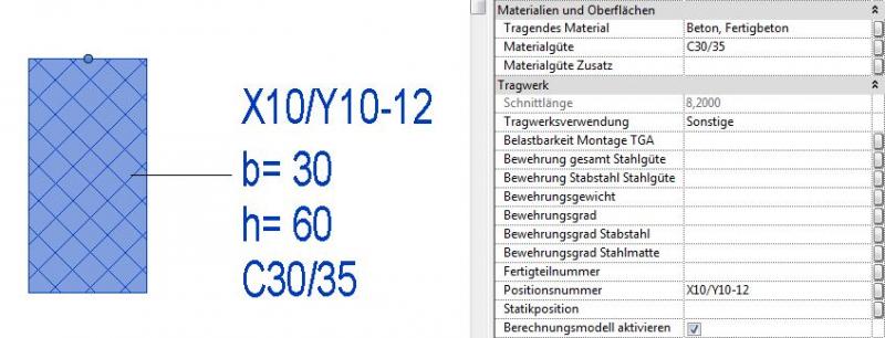
Material assignment for graphical representation: This is done by selecting the option in the member parameters > Load-bearing material in the project (here using a reinforced concrete beam as an example):
In this phase, members are supplemented with structural design information, and the structural framework is further detailed. Secondary members of the structural system (such as purlins, rafters, struts, and similar elements) are modeled.
Presentation
The various states differ in how they present the agencies.
![Plandarstellung[1].jpg](/media/135029B52B76F58139D7736C91D43683/plandarstellung[1].jpg)
Features
Feature
- Ground-contacting element
- U-value
Parameters
Outline Information
Labeling
In this phase, members are labeled only in the structural design drawings:
- Load diagram: Load application
- Position plan: Position
- Architecture: Labeling of the top and bottom beams
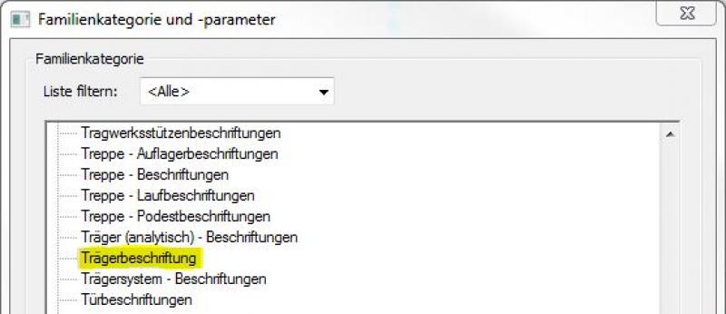
New labels can be created using the label family template >M_General Label. In the new family, the category should be changed to "Beam Label" using the >Family Category and Parameters command (Note: not "Skeleton Construction Label"!)
Instructions
Revit offers a range of features for modeling secondary structural elements of the structural system. These include:
- Beams: The >Civil Engineering >Beams command can, of course, also be used to model secondary beams:
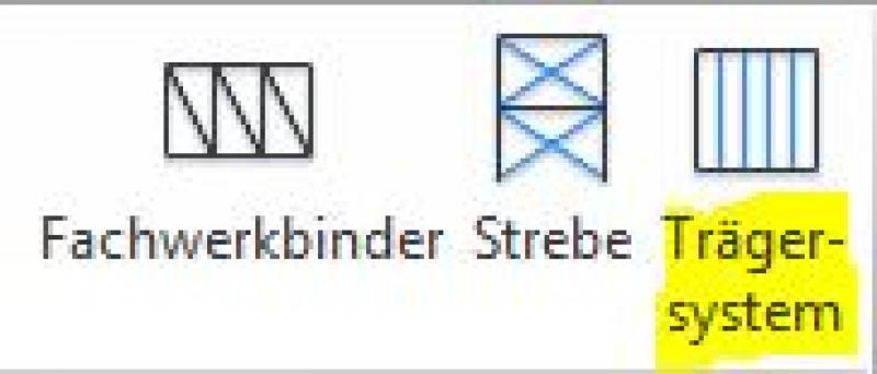
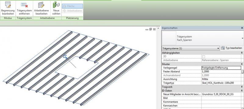
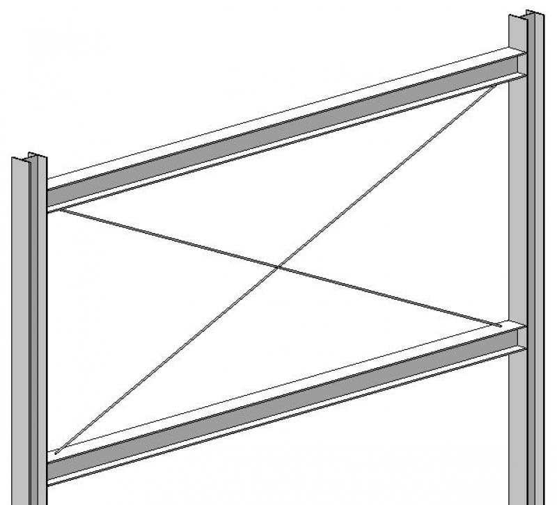
- Truss System: The command >Civil Engineering >Truss System is used to create a series of parallel trusses, such as rafter systems in a pitched roof. An advantage of using this command is the ability to efficiently create system breaks—such as around openings—using simple boundary lines. The beam family or type to be used in the system can be set in the Properties window under >Beam Type:
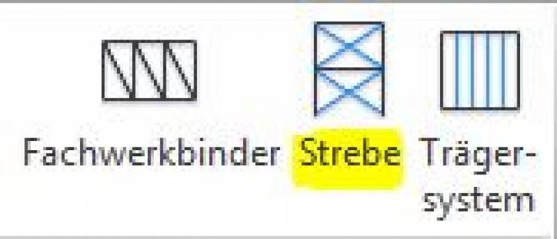
- Brace: The command >Civil Engineering >Brace is used to create diagonal bracing elements, such as tie rods in wind bracing systems. The advantage of using this command is that the braces are automatically connected to the beams and columns of the primary structure and can be trimmed individually. Any family from the Skeleton Structure category can be used as a brace:
- Truss: This command plays a special role and is therefore covered in a separate article. See this link: Truss
At this stage, at the latest, a further distinction is made between the various design options for structural components. For example, a distinction must be made between cast-in-place and precast beams.
Presentation
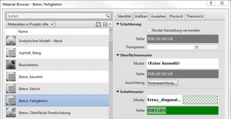
This is where the different countries differ: In Austria, submission drawings are color-coded by building material. This classification is based on the reinforced concrete classification specified in the Vienna Building Code.
Features
Labeling
During this phase, structural members are marked as "ready for approval" by the architectural team.
These include:
- Beams - Cross-sections (width x height)
- Beams - Heights: Top edge, bottom edge
Instructions
Country-specific color settings:
In Revit, the specific color schemes for submission drawings (permit drawings) are defined in the material (there is no type setting for the color fill at a coarse scale for beams): Color in the material:
Additional features are entered into the component properties (parameters) as described above so that they can be used for labeling:
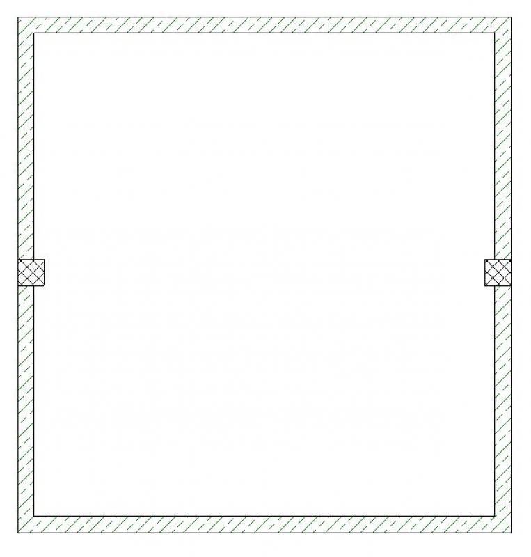
Hidden representation of joists/beams in floor plans:
In many cases, joists and beams must be displayed as hidden elements (with dashed lines) because they are generally located above the section plane of the floor plan. Although Revit does not offer a direct function for this, the desired dynamic result can be achieved by creating a second floor plan with the appropriate section height, including specific settings.
The following procedure is recommended in this regard:
- Preparation of the standard floor plan without additional steps
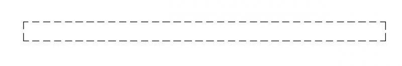
- Creation of a second floor plan with a section plane in the area of the joists/beams to be hidden
- Visibility settings in the second floor plan: only the "Skeleton Structure" category is visible with section lines - Override > Hidden lines, View style: Wireframe
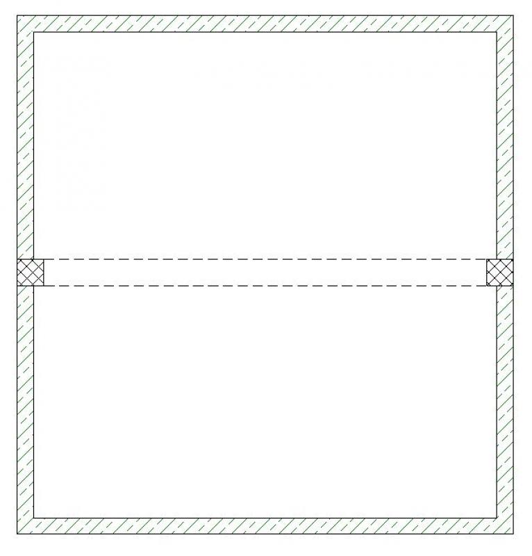
- Aligning the conventional floor plan and the second floor plan so they overlap on a single drawing
In other words, it only appears on the map in the desired combined view:
Example illustration:
Floor plan 'conventional' + 2nd floor plan 'hidden' = 'Combined' floor plan
Model illustration:
During this phase, all information required for the assignment (concrete grade, etc.) is added to the members. In addition, the member is reinforced. Depending on the collaboration scenario, this can be done in 3D within the member or in 2D, independent of the model.
Presentation
Plan view (cross-section)
Model representation
Features
- Reference
- Undervoltage
Parameters
- Gross weight
- Net weight
Outline Information
Labeling
During this phase, the substrate is fully labeled and marked.
Architectural Floor Plan:
- Dimensioning of all beam edges and beam cross-sections
- Lower and upper edges of beams
Structural Design Overview:
- Dimensioning of all beam edges and beam cross-sections
- Beam bottom and top edges
- All information relevant to the structural shell
Instructions
The information regarding the reinforcement to be used in this phase must be provided by the structural engineering team and incorporated into the foundation design.
For instructions on creating new families in the "Support Labels" category, see the guide in this article under the section >Design >Labeling >Revit Workflow
Hiding lower beams/joists in floor plans:

Unfortunately, this content is available only to our Pro users.
If you'd like to read the full article, try the Pro account or become a Pro user.