At this stage, it is not necessary to include a representation of a staircase. However, it is recommended that you include a placeholder; see Conceptual Modeling.
A staircase is designed for the first time during this planning phase.
Presentation
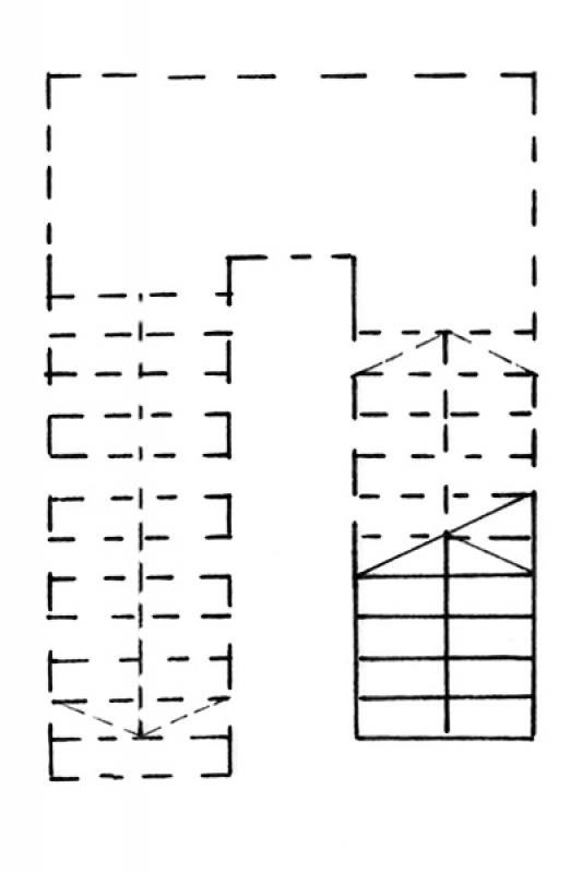
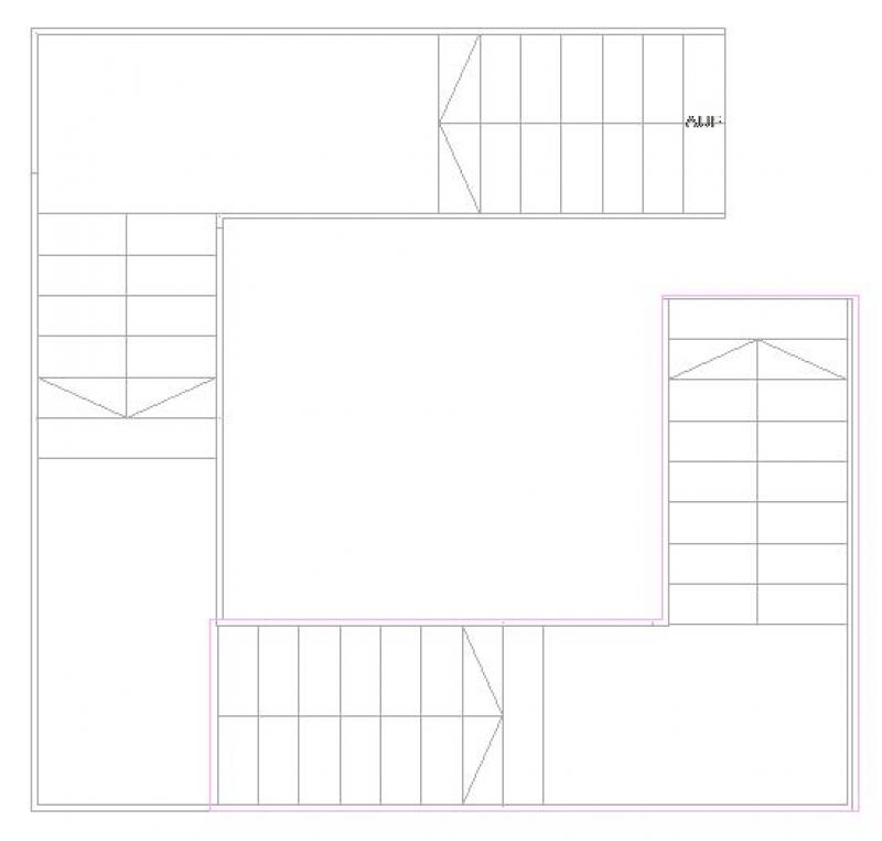
Figure 1
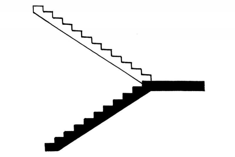
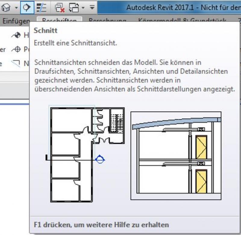
Figure 2
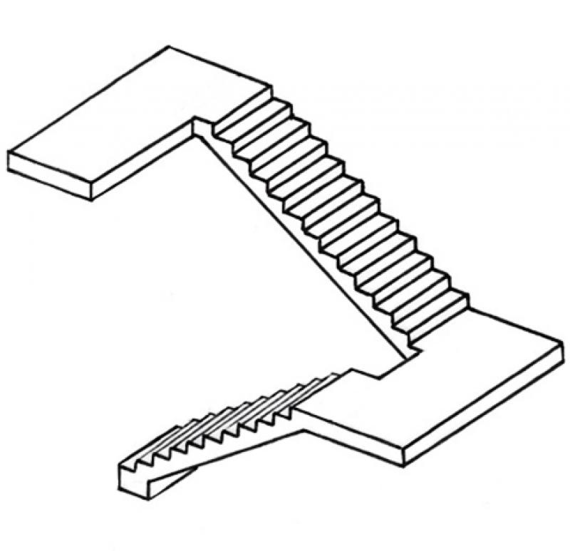
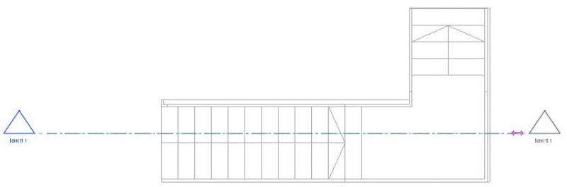
Figure 3
Features
The following key features are defined in this phase:
- Geometry (number of rungs, rungs-to-rungs ratio, tread width)
- Location
Feature
- Number of performances
- Number of podium finishes
- Number of inclines
- Accessible
- Fire resistance class
- Emergency exit
- Reference
Parameters
- Wide stance
- Overall height
- Height of inclines
Outline Information
Labeling
At this stage, it is not yet necessary to label the component.
Instructions
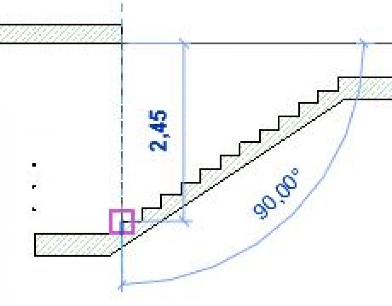
Stairs are defined by the following criteria:
- Rise (calculated by dividing the floor-to-floor height by the number of steps)
- Tread depth
- Tread depth
- Landing depth
- Location of the bottom bend line
- Location of the first and last risers (on the intermediate landing)
- Location and shape of the handrail
Note: Of these 7 criteria, a maximum of 6 may be defined.
In the early stages, stairs are always created as draft stairs and are only converted into the appropriate types (shell construction / finishing) in later stages.
The baseline for the staircase should always be on the "fixed" side. For example, in stairwells, this would be on the side of the stairwell wall, not on the side of the stairwell opening. For freestanding staircases, the center of the tread is recommended as the baseline.
Stairs with tapered runs should first be modeled as a "Component" staircase and then converted to a "Sketch" staircase after the rise-to-run ratio has been defined.
Note:
- The landing depth must match the run width; otherwise, Revit will display a warning.
- Stair types are composite components that include a defined flight type and a defined landing type. Therefore, the stair type designation should always clearly indicate which flight or landing type is being used.
- If the floor-to-floor height is the same, the stairs can be constructed over multiple floors.
Create:
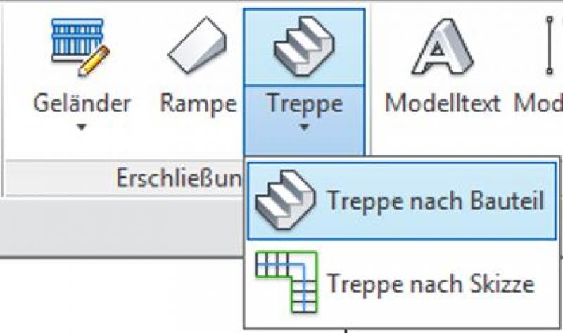
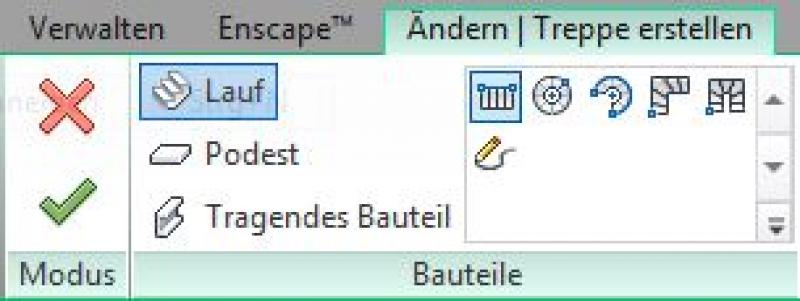
In the Architecture tab, you can create a staircase by selecting Staircase -> Create Staircase from Component.
Once you have set the correct constraints or levels for the start and end of a staircase in the Properties window, you can begin sketching the staircase.
Select the staircase type (choose the type of flight: spiral in full turns or straight, etc.) and the component with which you want to start modeling (e.g., flight, landing, or load-bearing component).
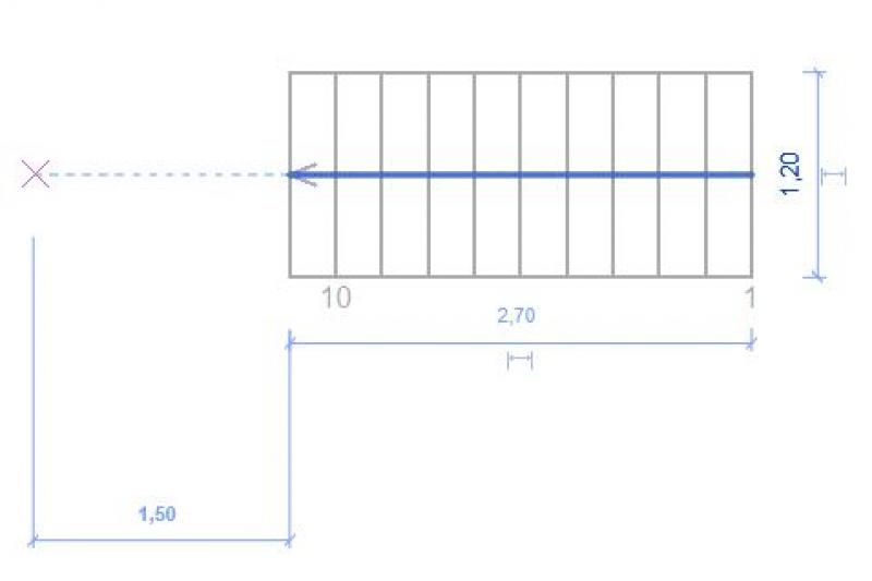
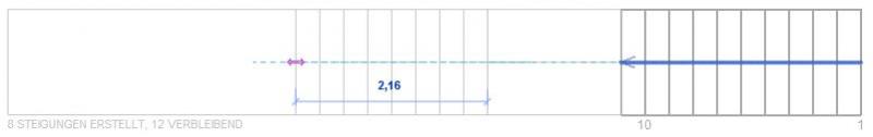
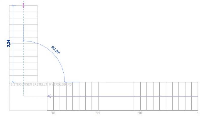
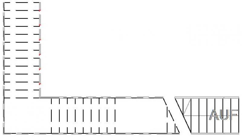
Next, sketch the staircase with the desired layout on the selected floor plan. Make sure to adhere to the minimum landing widths and the maximum number of steps in each flight up to the next intermediate landing (be sure to follow applicable standards):
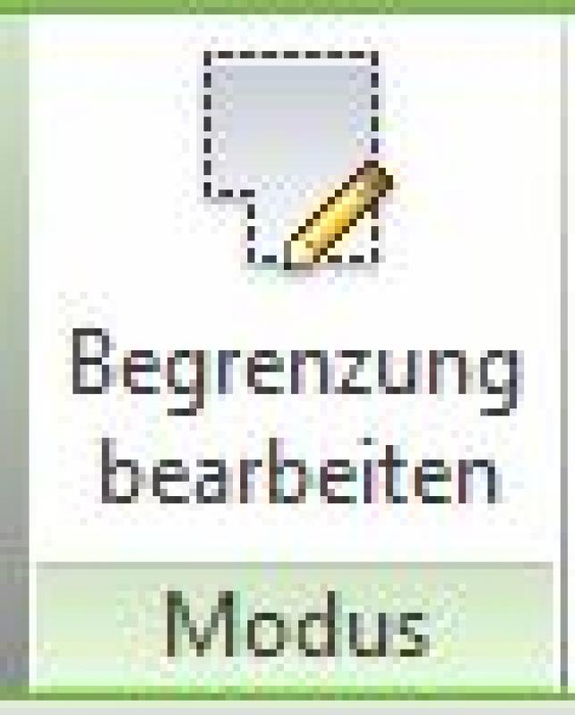
Now go to the floor plan above (stair landing) to sketch a ceiling opening. To do this, select the floor slab to be cut through and, if necessary, select the floor in a subsequent step if it already exists. Then switch to sketch mode using the "Edit with Boundary" command.
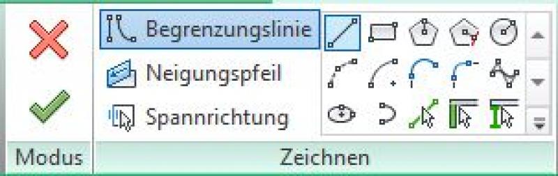
Use the drawing tools provided to draw the outline of the opening. The staircase below will be displayed as semi-transparent while you do this.
After creating a closed loop, exit sketch mode as usual by clicking the green checkmark. The ceiling cutout has now been created.

The next step is to create a test cut to verify that the required clearance height is met. To do this, select the cut icon.
Place the piece of fabric at the appropriate length across the staircase to be inspected.
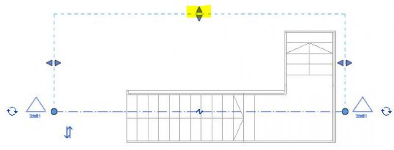
You can use the arrows to resize the selection area to the desired size.
Double-click the section icon (arrow) to switch to the section view, and use the Measure tool to check the clear height.

If the headroom is sufficient or meets the standards, you can proceed using the method described earlier (see in-situ concrete stairs).
If the distance between the step and the ceiling is not large enough, switch back to the ceiling or floor editing mode and adjust the boundary accordingly.
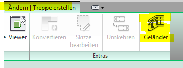
When creating stairs using system families, a railing is usually generated as well. If you do not want a railing, you can deselect it using the "Railing" button before modeling the stairs.
From this point on, a distinction is made between the different types of stairs:
- Structural stairs made of cast-in-place concrete
- Shell-stage staircases made of precast concrete
- Steel stairs
The template provided by BIM Office Administration includes basic stair types. Additional stairs can be found in the associated family library.

Unfortunately, this content is available only to our Pro users.
If you'd like to read the full article, try the Pro account or become a Pro user.