Unlike parapets, railings are non-solid fall protection barriers and are used on stairs, balconies, ramps, and galleries.
Depending on the authoring software used and its specific features, railings can be created in a variety of ways.
Given the wide variety of design options for railings, modeling them can be somewhat challenging. This article describes the basic approach.
At this stage, no railings are modeled yet.
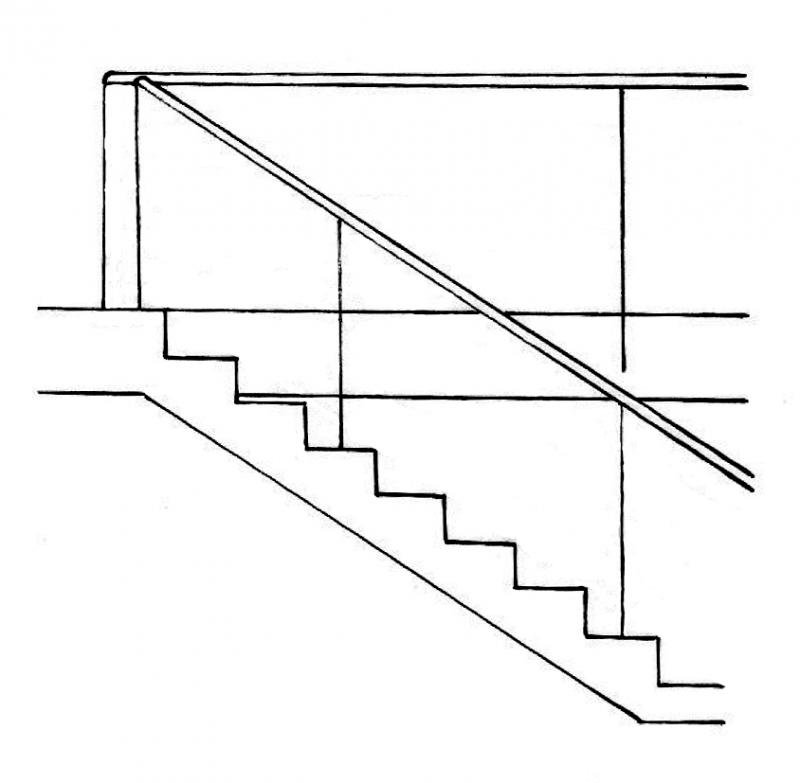
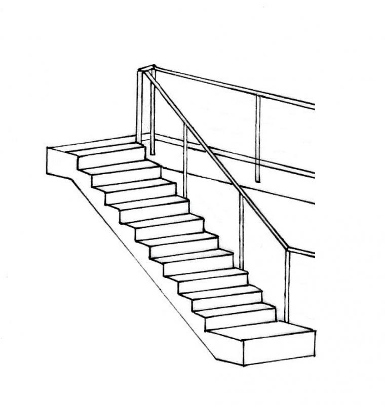
In this phase, handrails are generally not modeled yet. However, to verify the required escape route widths for stairs, for example, they are occasionally modeled at this stage, though they are usually deleted again afterward.
During the design phase, the component is created and assigned the appropriate material. To minimize modeling and modification efforts, railings are still represented in a highly abstract manner at this stage, e.g., as just a handrail.
Presentation
Plan view
Model representation
Features
In this phase, the following characteristics must be defined:
- Material Assignment
- Location
- Surface
- Geometry
Labeling
Handrails are not usually labeled separately.
Instructions
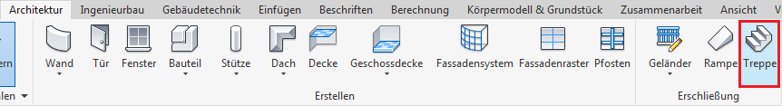
In Revit, railings belong to the category of the same name and are a special type of component in that they are often created automatically when modeling stairs. For this reason, the explicit Revit command “Railing” in the “Architecture” menu is used less frequently.
Railing modeling:
Basically, there are two ways to model railings:
1) Automatic generation when creating stairs:
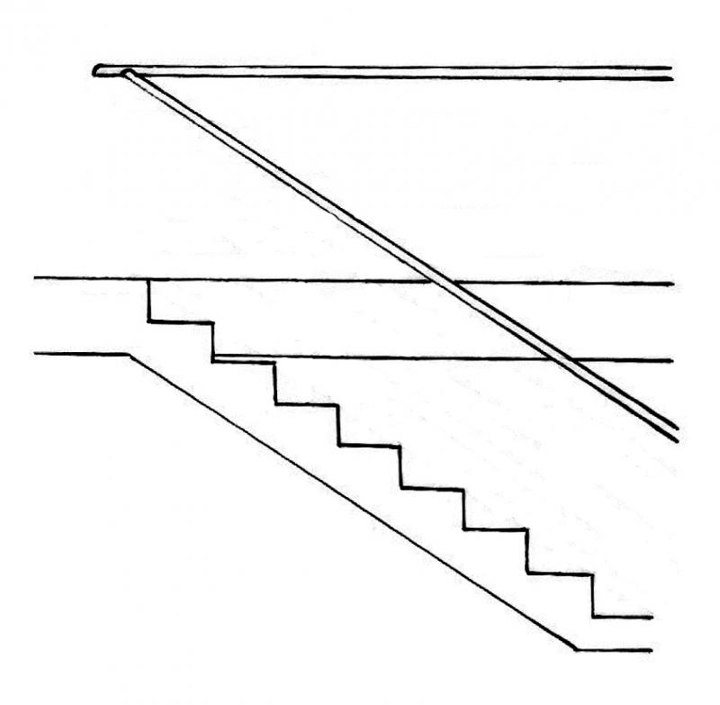
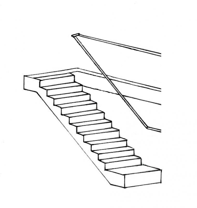
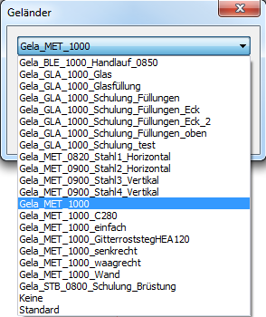
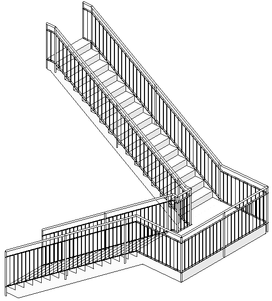
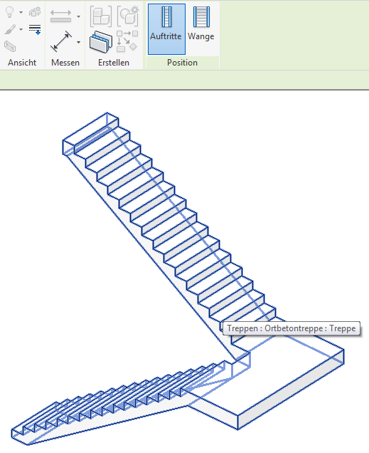
When you use the "Stair" command, select the "Railing" option, and choose a railing type (see the following images), the software automatically creates a railing along with the stair, whose path (i.e., the line sequence for the railing's longitudinal development) follows the outer edges of the stair.

2) Explicit modeling using the "Railing" command:
This command creates a single railing:
The other subcommands in the drop-down menu mean:
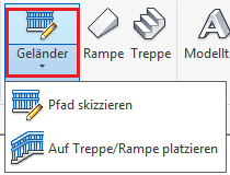
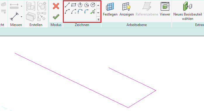
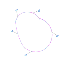
2.1) “Sketch Path”:
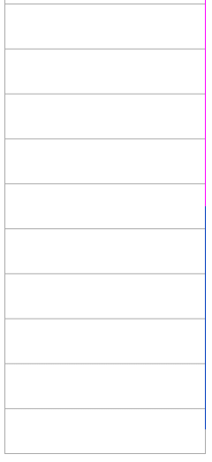
= "Free" modeling of a railing (i.e., independent of any other component) by drawing a path along the edge to be fitted with a railing (e.g., for a balcony railing or parapets of any kind). To create this continuous line chain, the standard drawing tools in Sketch Mode are available (see image; lines in magenta), with any diagonal path lines projected onto the floor plan plane for easier editing. ATTENTION: Revit accepts only one closed line chain per railing, meaning no breaks between the individual lines!
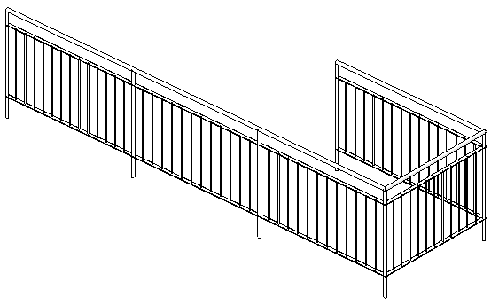
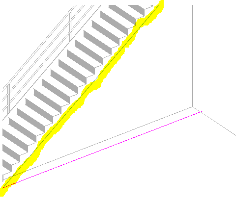
2.2) “Place on stairs/ramp”:
= Model a railing by selecting a base component (such as a staircase or ramp). The railing is placed along the outer edges of the base component, just as it is when created automatically:
2.3) Railings on floor slabs, walls, or terrain:
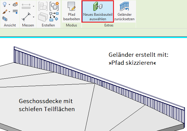
In addition to the commands mentioned above, it is also possible to modify an existing railing by making subsequent corrections to the base component. This is mentioned separately here because it allows you to place a railing on a sloped floor slab, a slanted wall top, or even on a topographic surface.
The following procedure is used:
- Creating a railing using the "Railing" command and "Sketch Path"
- Select the railing and use the "Select New Base Part" command in the ribbon
- Select a floor slab, wall, or topography
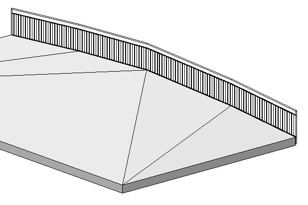
Before replacing the base component: The railing is straight After: The railing "follows" the edge of the floor slab
Components of a railing:
Railings are part of the system families and are therefore categorized by type in the project; these types, in turn, consist of a combination of components and, in some cases, external (i.e., "loadable") families.
A Revit railing therefore essentially consists of the following components, all of which are controlled by the railing type:
1) Handrail construction:
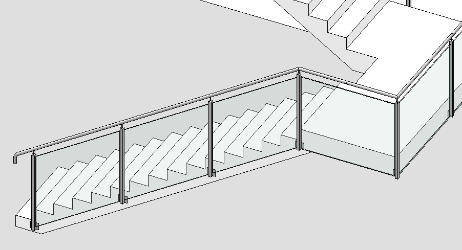
= all components that follow the path (i.e., the longitudinal direction) of the railing (shown in blue in the image):
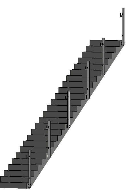
2) Baluster:
= all vertical components of the railing (shown in blue in the image); this includes not only the main railing posts but also all balusters (only the main posts are shown in the image):
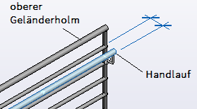
3) Upper railing stringer, handrails:
The top rail and handrails form the upper edge of a railing; the difference in the specific Revit terminology is shown in the following image: The handrail is not attached directly to the railing posts, but is a separate, laterally offset element.
In the current BOA environment, the Revit element “Upper Railing Post” is used as a handrail mounted centrally above the railing. Although this does not comply with Revit-specific guidelines regarding element usage, the functionality of the upper railing member and handrails is essentially the same.
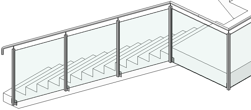
4) Fillings:
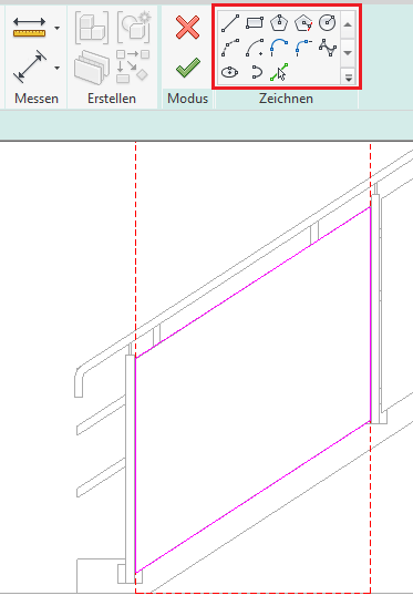
Fillers—such as glass panels, which are now commonly used in construction—are modeled separately in the BOA environment because Revit’s railing functionality is unfortunately limited in this regard. Since these elements are, in the broadest sense of the word, balustrades, facade walls are used as a substitute, which can be shaped into the desired form by adjusting their profiles. See also the instructions under Glass Panels.
Railings - Settings:
Assembling the components mentioned above in Revit is relatively complex due to the extensive range of railing features and presents a certain challenge. The following section provides a detailed description of all key railing settings, using a simple, "everyday" railing type as an example.
TIP: For a quick explanation of terms in Revit, we recommend hovering your mouse pointer over a parameter and reading the explanation that appears after a brief delay (known as a tooltip; often accompanied by an image).
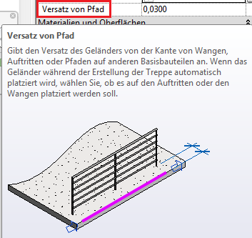
1) Instance parameter settings:
This setting is available in the Properties window:
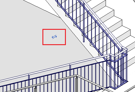
- "Path Offset": Controls the offset of the entire railing relative to the path line (shown in magenta in the image); the direction of the offset can be selected using the 'Flip' function (blue double arrow; see image), which is always displayed in the center of the railing (NOTE: this is often not visible in close-up zoom views!)
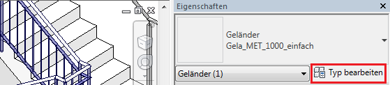
2) Type parameter settings:
After selecting a railing and using the "Edit Type" command, the settings are available in the Type Properties window:
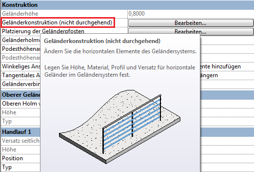
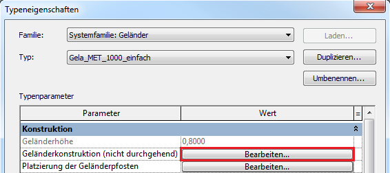
2.1) Handrail construction (non-continuous):
The "Edit" command next to "Handrail Design" (see image) opens another editing window where you can configure all components that follow the handrail's path (i.e., its longitudinal alignment):
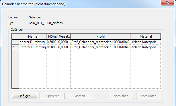
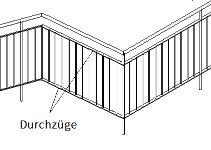
Lines 1 and 2 in this sample list correspond to the top and bottom ends of the balustrade spandrels, which are commonly referred to as “spandrels” in the construction industry. The individual columns in this table represent:
- Name: = a name of your choice for the element. Additional elements can be created using the "Insert" command (bottom right), deleted using "Delete," or reordered using "Move Up" and "Move Down."
- Height: = the height of the element relative to the top edge of the base component (usually the top of the staircase). The position of the cross-section profile within the profile family defines the edge to which the height refers (see Profile below). This is usually the centerline of the profile, which is why half the profile height must be subtracted to determine the correct position of the top edge.
- Offset: = the lateral distance from the path line
- Profile: = the cross-section profile used for the element, represented by a profile family and a type created within it; example: Prof_Gelaender_rechteckig (= family) : 0008x0040 (= type); Another profile can be created by creating a new profile family using the family template M_Profil.rft.
- Material: self-explanatory
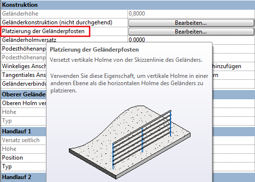
2.2) Placement of the railing posts:
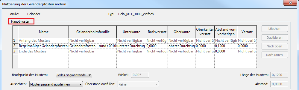
The "Edit" command next to "Railing Post Placement" opens another editing window where you can configure all vertical elements of the railing (i.e., posts):
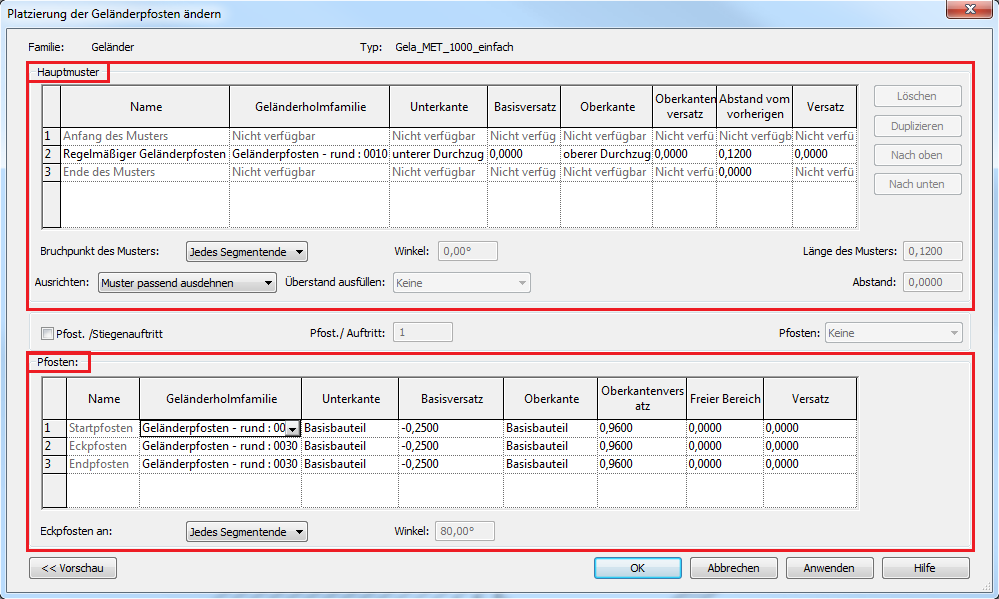
The two tables in this window represent (highlighted in red in the image above):
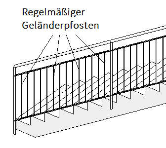
- Main Pattern (= top table in the window): contains all settings for a repeating pattern of balusters, which is most often used for the regular arrangement or spacing of infill balusters between the main posts of the railing (see image below)
- Posts (= lower table in the window): contains all settings for the design and positioning of main posts (= elements for securing the railing; see image below)
Given the standard approach to building railings, the table below, which lists the settings for the main posts, is described first:
2.2.1) Posts:
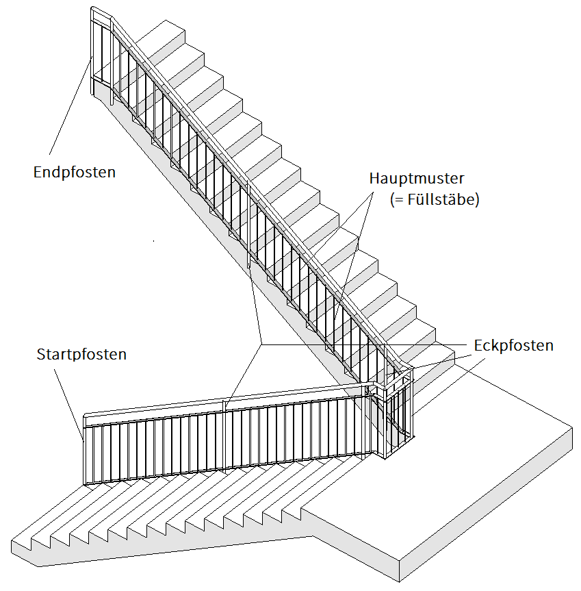
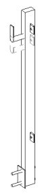
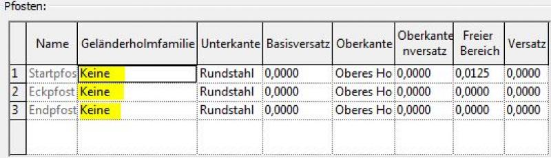
The three rows in the "Posts" table below mean the following (see image below):
- 1 Start post: = the first main post at the start of the railing path, marked with a blue arrow pointing in the direction of the railing. You can change the direction of the railing by clicking on this arrow!
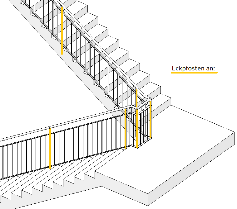
- 2 Corner posts: = all main posts along the rest of the railing. However, the term 'corner posts' is somewhat misleading, as it also includes posts located along a straight but segmented railing path (see image above). ATTENTION: The position of corner posts is set in the “Corner posts at:” setting (described below).
- 3 End posts: = the last main post at the end of the railing path, also marked with a blue arrow pointing in the direction of the railing.
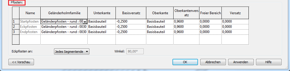
The columns in this table represent:
- Name: = a name specified by Revit (and therefore "grayed out") for the corresponding post position
- Balustrade post family: = the post family used for the element and a type created within it; example: Balustrade post - round (= family) : 0030 (= type); A new post family can be created using the family template M_Railing (Post).rft and loaded into the project.
- Lower edge: = Lower edge of the post relative either to the upper edge of the base component (e.g., staircase) or to an element defined in the railing design (openings); select via a drop-down menu
- Base offset: = Offset value relative to the bottom edge (= base) of the post
- Top edge: = Top edge of the post relative either to the top edge of the base component (e.g., staircase) or to an element defined in the railing design (spandrels); select via a drop-down menu
- Top edge offset: = Offset value relative to the top edge of the post
- Free Area: = Distance of the post from its original position in the longitudinal direction of the path; positive value = displacement in the direction of the path; negative value = displacement against the direction of the path
- Offset: = Distance of the post across (= laterally) the path’s longitudinal direction
Additional settings in the "Posts" section:
- Corner posts at: = the positioning of corner posts along the railing path. Here, the following applies: “Every segment end” = a corner post at every end of the path line; “Angle greater than” = corner posts at those positions where the railing forms a corner with a specific angle (angle specified to the right under “Angle”); “Never” = self-explanatory
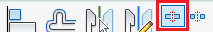
Placement of main posts at precisely defined locations (recommended by the author of this article):
In many cases, it is desirable to position the main posts at specific locations along the staircase. The following procedure is recommended:
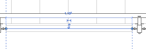
- Setting »Corner posts at:« »End of each segment«

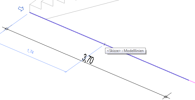
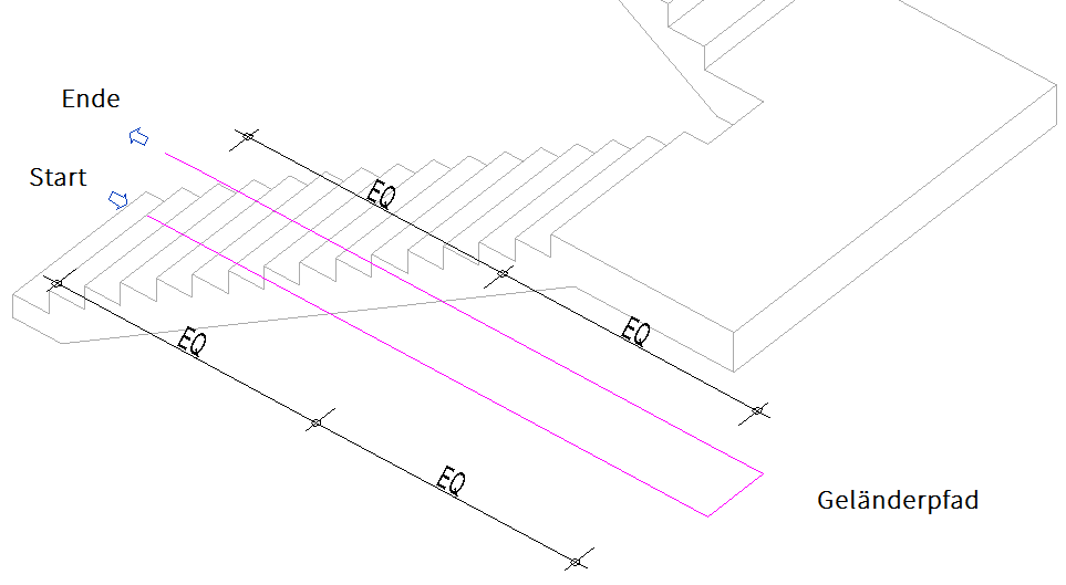
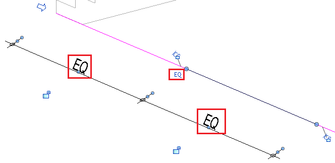
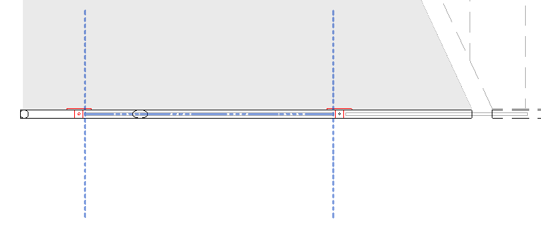
- Determine the midpoint between two endpoints: Create a dimension using the "Aligned Dimension" command, reference the three endpoints, and use the "EQ" (= equal) function to set the values of the two dimension numbers equal. This moves the middle point exactly to the center of the two outer points (see image):
- The "At the end of each segment" setting creates an additional "corner post" at the new end of the line (as mentioned, the term "corner post" is misleading for this reason)
2.2.2) Main pattern:
The rows in the table above titled "Main Patterns" mean the following (see image below):
- 1 Start of pattern: = represents the position where the spacing of regularly repeating balusters (= infill bars) should begin; ATTENTION: This line is always disabled (= 'grayed out') due to its dependency on the "Pattern Breakpoint" setting (located below the table on the left) and the positions specified by it
- 2 Regular Baluster: = the baluster family used for the repeating element and a type created within it; Example: Baluster - Round (= Family) : 0010 (= Type); A new post family can be created using the family template M_Railing (Post).rft and loaded into the project. Using the >Duplicate command (to the right of the table), an additional row can be created for another infill rail. However, multiple regular railing posts only make sense if the sequence (= pattern) is intended to include alternating different infill bars!
- 3 End of pattern: = represents the position where the spacing of regularly repeating balusters (= infill bars) should end; As with "Start of Pattern," this is always disabled (= grayed out) due to its dependency on the "Pattern Breakpoint" setting
The columns in this table represent:
Since this table differs from the "Posts" table below by only one column, we refer here to the descriptions in section 2.2.1) Posts and explain only the column that differs:
- Distance from the previous one: = the distance between the repeating, regular balusters (= vertical rails). In most cases, the maximum spacing required by many standards for vertical railing elements is entered here: 12 cm (possibly more, depending on the bar cross-section). NOTE: The value for "Distance from previous" in the "End of pattern" row should always remain set to 0.00. Otherwise, this value will be added to the top spacing (12 cm), which ultimately results in incorrect, excessively large spacings!
Additional settings in the Main Pattern section:
- “Pattern breakpoint:” = the specification of the positions (= breakpoints) between which the spacing of the infill bars (= pattern) is to be determined. Here, the following applies: “Every segment end” = a break point at every path line end; “Angle greater than” = a break point at those positions where the railing forms a corner with a specific angle (angle specified to the right of it under “Angle”); "Never" = self-explanatory; General recommendation: In "Breakpoint of the pattern:", it makes sense to always select the same setting as in "Corner posts at:"!
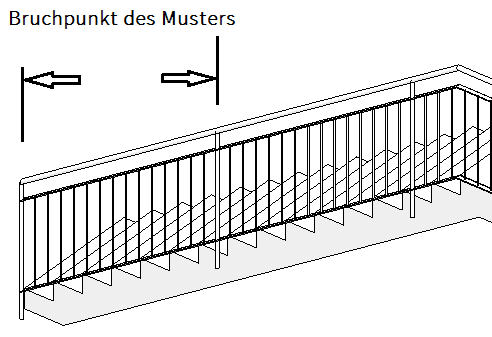
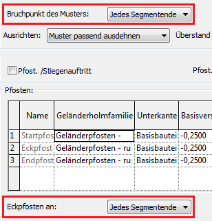
- “Alignment:” = specifying the starting position from which the distances for post placement should be measured (see image below). Here, the terms mean: “Start” = the distances are marked starting from the beginning of the pattern (disadvantage: a residual distance remains at the end); “End” = the distances are marked starting from the end of the pattern (disadvantage: a residual distance remains at the beginning); “Center” = the distances are marked starting from the center of the pattern on both sides (disadvantage: a residual distance remains at both ends); "Scale pattern to fit" = the distances are applied evenly, approximating the specified value as closely as possible (recommended!)
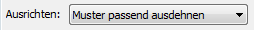
The "Stretch pattern to fit" setting means that between the start and end of the pattern (= breakpoints), just enough posts are placed so that the spacing value comes as close as possible to the specified distance but does not exceed it (due to the risk of falling between the bars). For example, with a value of 0.12, enough posts are placed so that the distance between the infill bars is less than 12 cm. This Revit feature most closely matches the actual construction process of the railing and is therefore recommended!
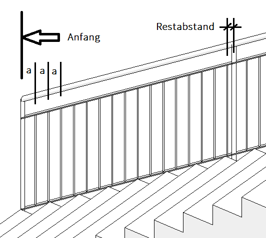
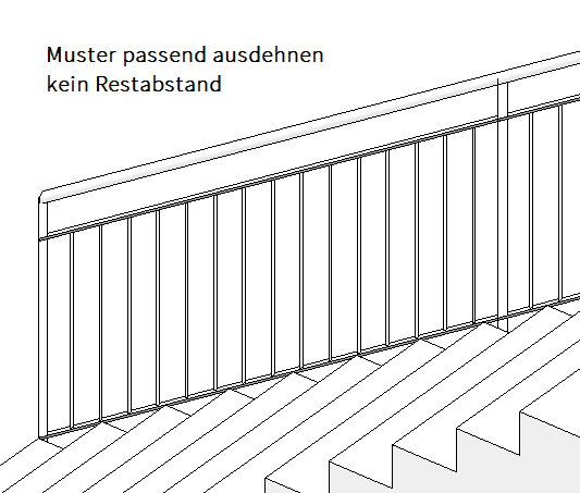
Example of "Align:" with the "Start" setting "Stretch to fit pattern" setting
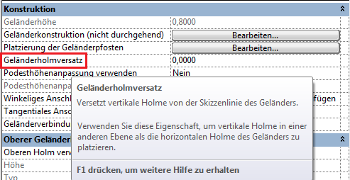
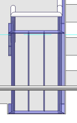
2.3) Handrail offset:
Controls the offset of the railing rails; only railing rails, handrails, and posts are affected by the offset. The elements of the railing structure (crossbars) are not affected! (see image):
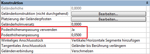
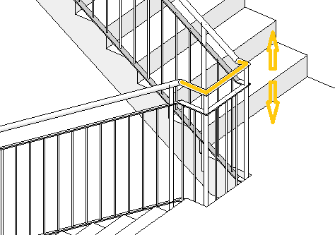
2.4) Platform height adjustment:
Determines the height of the railing in the landing area.
Two steps are required to perform this elevation correction:
- Use landing height adjustment: "Yes"
- Landing height adjustment: Specify height value (positive = higher, negative = lower than general height)
2.5) Angular connector, tangential connector:
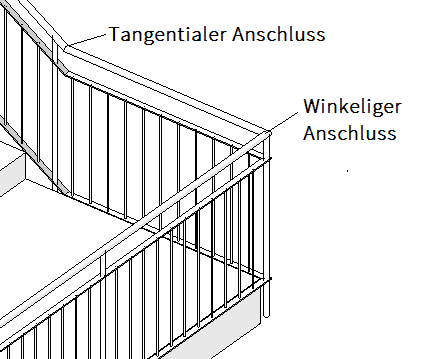
Angled connector:
Controls the connection of the railing (= 'connectors') at points where the railing forms an angle in the floor plan. For example, at the corner of a landing (see image above)
Possible settings:
- Add vertical/horizontal segments (recommended): see image
- No connector: open terrain areas where there is a difference in elevation
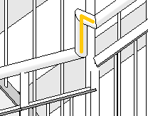
Tangential connector:
Controls the transition of the railing (= 'connectors') at points where the railing forms an angle in a view. For example, at the transition from a run to a landing (see image above)
Possible settings:
- Extend railings until they touch (recommended): Elements are extended and mitered until they touch
- Add vertical/horizontal segments: segments are added when there is a height difference (see image below)
- No connector: If there is a height difference, no connection is created
2.6) Handrail connection:
Determines how railing components are connected.
Settings options:
- Trim = cuts elements at a right angle
- Fusion = joins the elements with a miter cut (recommended)
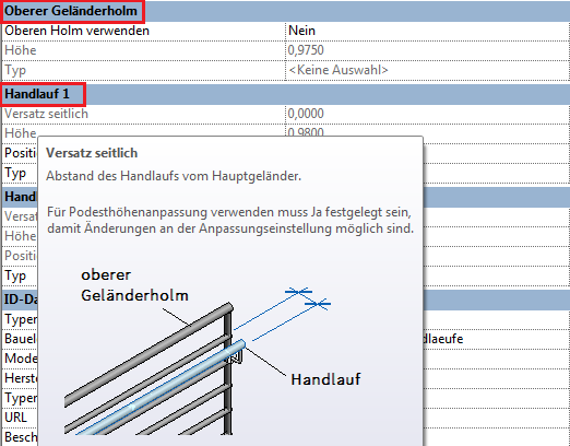
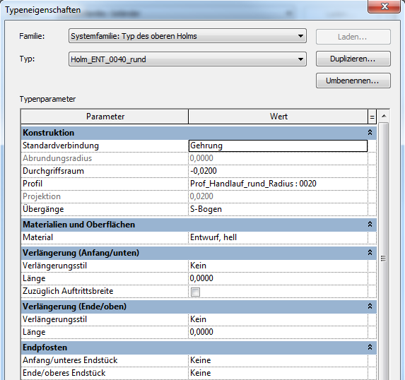
2.7) Upper handrail:
The >top rail forms the top edge of a railing (see image)
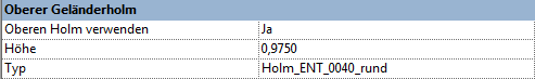
Settings options:
- Use top spar: yes/no = self-explanatory
- Height: self-explanatory
- Type: Clicking in the field to the right of "Type" opens another, very comprehensive window for configuring the upper railing rails:

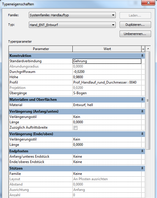
2.8) Handrail 1, Handrail 2:
The handrail of a railing functions similarly to the top rail (see image above), with the difference that the handrail is positioned at a distance (offset) to the side of the path, which also makes it possible to install two handrails on a single railing:
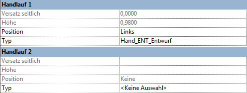
Settings options:
- Side offset: controls the distance between the handrail and the railing path
- Height: self-explanatory
- Position: Left, Right, Both
- Type: Clicking in the field to the right of "Type" opens an additional, very comprehensive window for handrail settings:

Independent handrail guide:
Handrails and the top rail can also be extended independently of the rest of the railing structure; the "trick" lies in selecting the element separately.
The following procedure is used:
- Use the Tab key to select the handrail or top rail
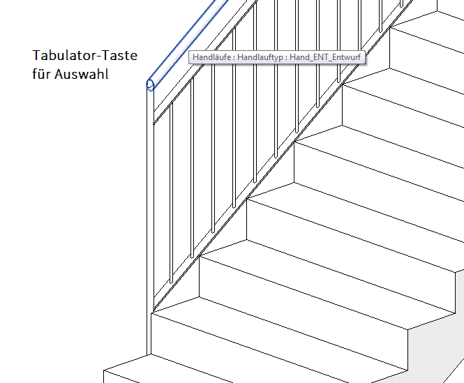
- "Edit Railing" command (on the ribbon)
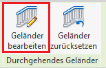
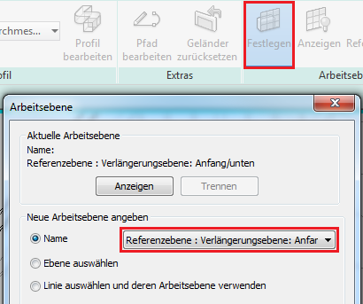
- Select the working plane using "Set": to choose whether to finish the top or bottom end of the handrail
Settings: Reference plane: Extension plane: Start/bottom ... : End/top
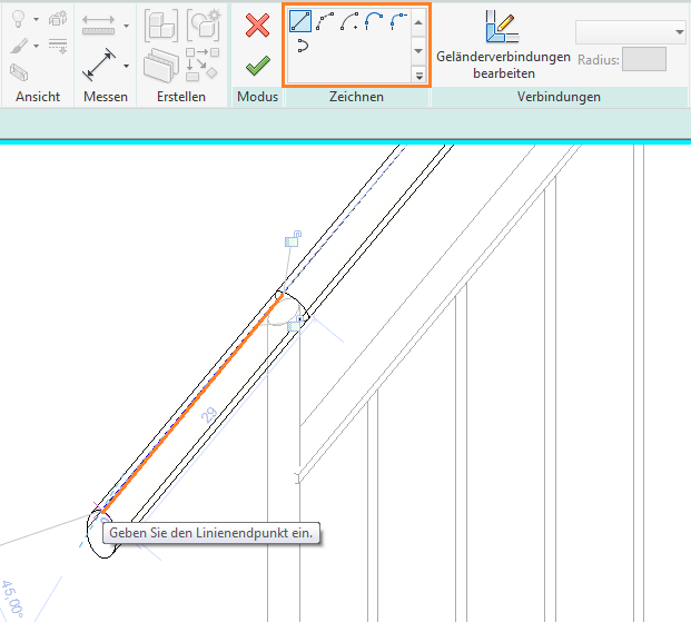
- Use the "Edit Path" command to continue the railing:
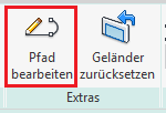
- Extend the path using drawing tools:
Limitations of railing functionality in Revit:
- Corner posts present a limitation when modeling railings. Unfortunately, it is not possible to set more than one corner post type for a single railing type, which inevitably leads to the need to divide a highly detailed railing with a LOD higher than "LOD300" into different types.
- Another limitation arises when modeling railing infills. Instead of labor-intensive railing elements, the BOA environment uses the facade wall workaround mentioned earlier, which is explained in the following section.
Modeling of facade walls for infill panels (instead of railing elements):
The following procedure is used:
- Create a wall using the "Wall" command, "non-load-bearing wall"; Type: Gela_GLA_0010_Glass_Filling
- Model a wall in the floor plan between two main posts
- Adjust the wall in the view using the "Edit Profile" command:
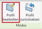
- Use drawing tools to adjust the profile:
Special Case: Steel Staircase
A separate workflow is required for steel stair railings. This is covered in the article "Stairs: Steel Stairs," since the steel stringers are designed in conjunction with the railing families and are therefore part of the stair structure.
Railing along a floor slab:
- Select a path for the railing


- Lock the path to the edge using a pin
- Select the desired railing type, or use the type editor to edit the type or create a new one.
Handrails along a staircase:
- Stairs are modeled with handrails included
- The railing type can be changed later in the Properties window
- Create new profiles as a family (profile families)
- If the path is modified, it should be locked to the edge again (lock)

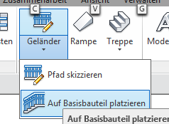
When creating a new object, select the command "Railing -> Place on Base Component" (this also applies to ramps):
ArchiCAD is designed to allow for a quick and seamless transition between phases. You can prepare sections for any desired level of model maturity and assign custom model display options to them. In the model views, you can define global maturity levels for model elements so that you don’t have to adjust each element individually.
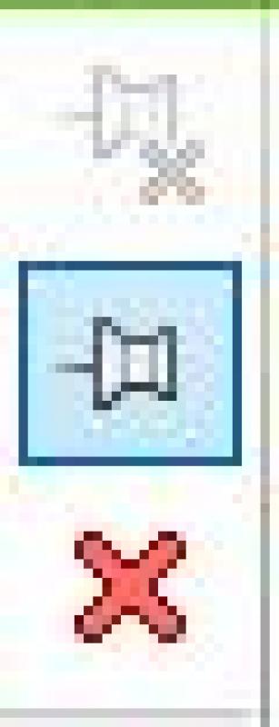
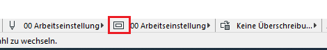
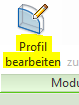
We have prepared a brief guide on the railing. You can find the model display dialog box under the menu item
Documentation
à
Model representation
à
Create a model...
Apart from any necessary adjustments, no additional steps regarding the railing are planned at this stage.
Building code requirements must be taken into account, and the plan must be modified to comply with official regulations.
Presentation
Plan view
Model representation
During this phase, any specifications relevant to the tender may be added to the component.
Presentation
Plan view
Model representation
Features
The extent to which the existing specifications are sufficient for the request for proposals or need to be supplemented should be clarified with the project management.
Labeling
Handrails are not usually labeled separately.
Instructions
The design requirements for a railing during the construction phase often cannot be met using the railing features available in Revit.
This is especially true if you want a specific "spacing" between the railing posts. However, this can be achieved using the workaround described below. In this case, the railing is modeled as a facade.
Create:
Create a new family for balusters (Category: General Model), and then create a new baluster type:
In the railing type editor, select "Railing Rafter Families" from the drop-down menu under "Placement of Railing Posts" -> "Edit":
The posts are separated by the path:
Note:
In some cases, it can also be helpful to divide the railing into individual sections.
Facades as infill elements:
Example of use:
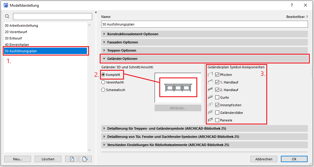
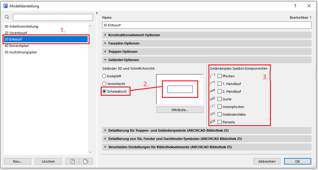
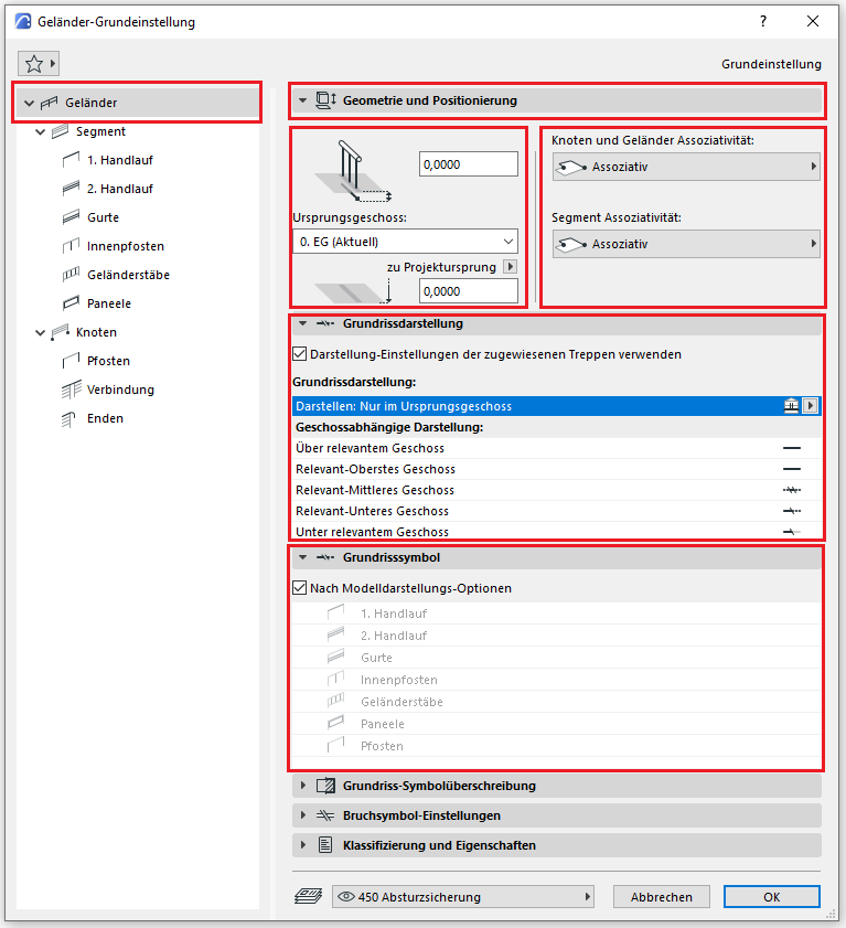
- Let's select a model display. We will use this for the execution phase in the detail sets.
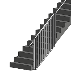
- This setting will detail the railing elements globally and uniformly in the 3D model area. The preview window shows how all parts of the railing are indicated.
- You can individually select which components of the railing should be displayed or hidden in the floor plan area. These options do not affect the 3D area. In the construction phase, specific elements of the railing are displayed.
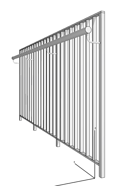
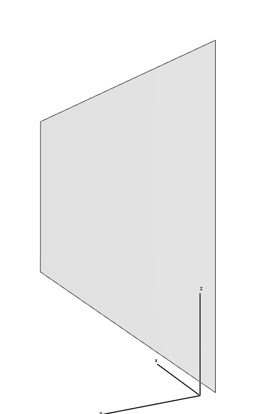
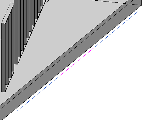
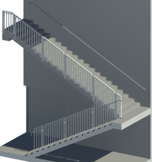
This is what the railing looks like in the 3D view with the full model displayed.
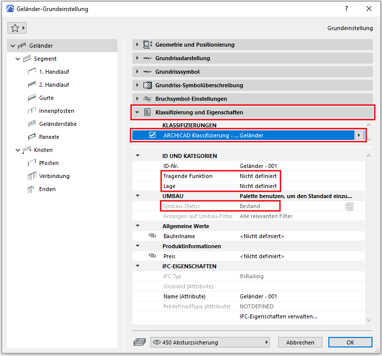
The new features and parameters added for this phase must be entered in the appropriate fields of the component's settings dialog.
The description of the settings dialog and the corresponding procedure can be found in an earlier phase description in this article.
The labeling and dimensioning of the component should always be associative. The description of the procedure in ARCHICAD can be found in the relevant articles.

Unfortunately, this content is available only to our Pro users.
If you'd like to read the full article, try the Pro account or become a Pro user.