Just like real buildings, digital building models are organized vertically into floors. On the one hand, this offers advantages for the necessary floor-by-floor visualization; on the other hand, quantity and mass calculations—for example, for bids—are also performed on a floor-by-floor basis. Floors thus form an essential hierarchical structure of building models alongside the object-type classification (e.g., walls, floors, and columns) and, in some programs, layer or section structures. For this reason, modeling in the BIM workflow is generally performed on a floor-by-floor basis. This article describes sensible floor structures in an interdisciplinary design scenario and outlines approaches for handling the few exceptions where objects are modeled across multiple floors.
An interesting question in an interdisciplinary planning scenario is which floor a rough slab belongs to. Structural engineers generally view rough slabs as being above a floor: their drawings rely on this definition; in their floor plans, they “look” through the slab from above, so to speak. Architects, on the other hand, tend to view the rough slab as the floor slab of a floor —after all, all elements “rest” on it, and even in a floor plan (e.g., at a section height of 1 m), a rough slab would not be visible (ceilings above the floor are nevertheless usually shown as dashed lines).
Issue
The question now is: where does a rough slab belong—below or above the floor?
Strategy
Especially when architectural and structural engineering teams collaborate closely using models, it is recommended to define the floor boundary at the top edge of the rough slab:
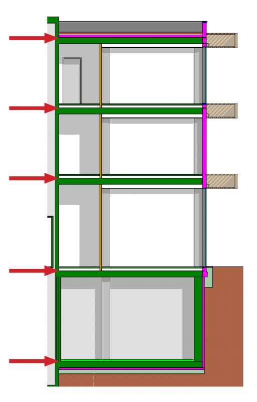
This allows all objects to be clearly assigned—floors, suspended ceilings, walls, etc., are clearly defined, and the rough ceiling lies above the floor level. One consequence of this approach is that a sort of foundation floor must be created. Many architects prefer to define the floor level based on the top edge of the finished floor—since this must also be specified in the sections. Additionally, certain programs, such as ArchiCAD, do allow for floor assignments of elements below a floor level. However, this is not recommended for interdisciplinary workflows.
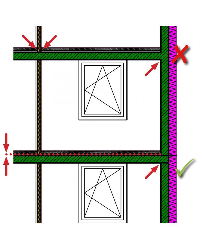
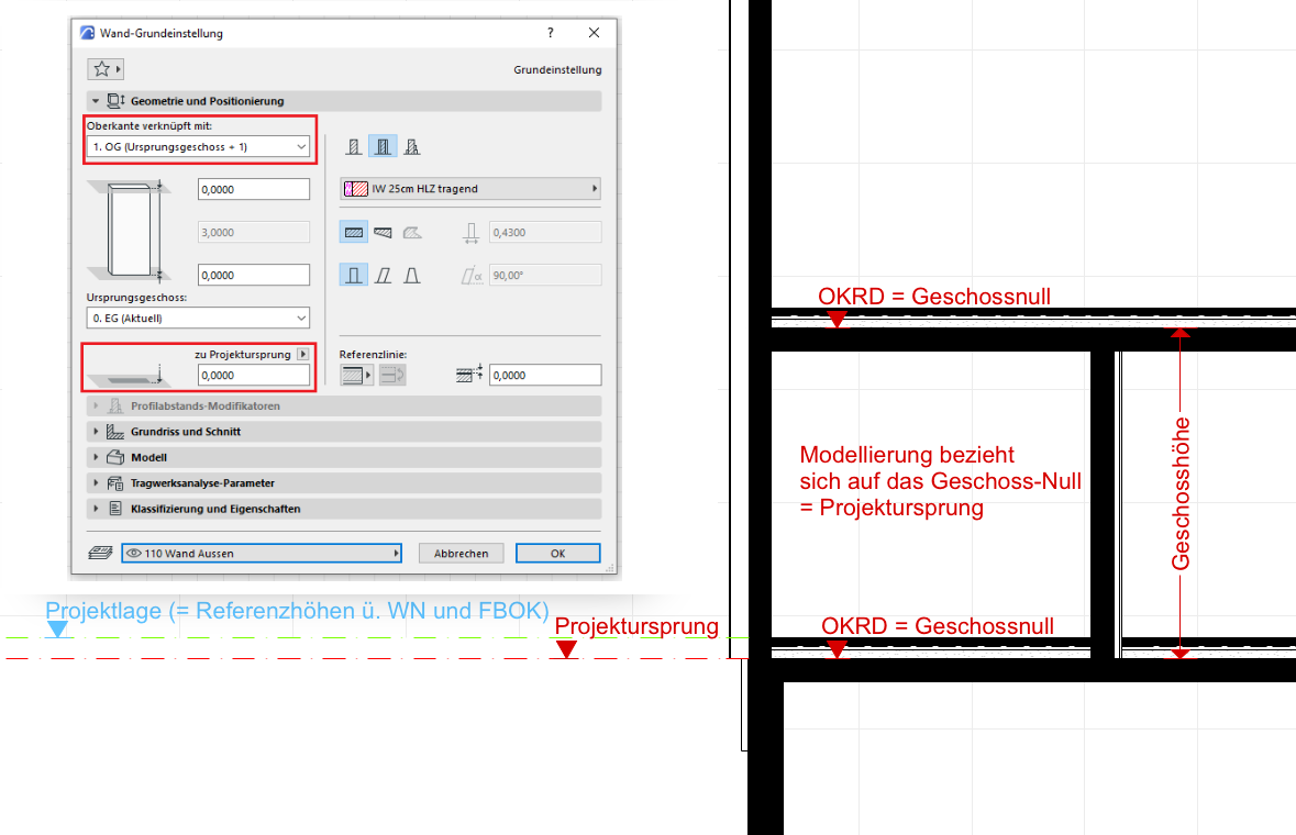
To ensure accurate mass calculation, it is recommended that all building components consistently end (at the latest) at the edge of the floor—the illustration above shows this using the example of the ceiling connection to the exterior wall: The insulation layer ends at the top edge of the floor slab, while the concrete wall extends below the slab.
Mezzanines or split levels refer to areas of a building that serve the building’s primary functions but differ from its main floor structure.
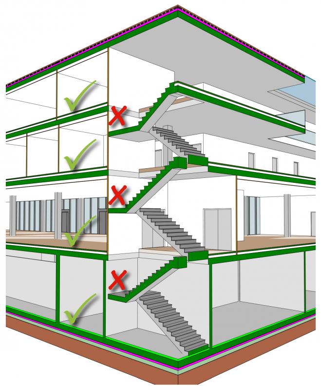
For example, stair landings or ramp landings that serve solely as access points should not be treated as a floor or split level (see sketch above).
As a general rule, a separate split level is created in digital building models when there is a deviation of approximately 1.50 m from the main floor level.
Split levels are handled differently in various BIM programs and still pose certain challenges for some applications, particularly when it comes to accurate graphical representation. In some projects, they are part of a floor with additional levels; in others, they form independent floors with their own floor levels, which differ from the main floors only in their floor designation.
It is important to consider the requirements early on, as making changes later on can be time-consuming.
For information on how to use the software, please refer to the relevant section in this article.
Although the general rule is to model elements on a per-story basis, there are often cases where elements extend across multiple stories. Examples include:
As is often the case, the general rule here is: model the structure as it is built. For example, a continuous two-story wall is naturally poured in a single pour—not floor by floor. In this process, the object is always assigned to the lowest floor it reaches. When planning a construction sequence, this also makes sense from the perspective of quantity takeoff—for example, how much concrete do I need to produce the multi-story elements of this construction phase?
The figure illustrates how to handle multi-story structural elements using the example of a structural column in a two-story building: The column belongs to the lowest story where it begins, in this case the ground floor. It is modeled as a continuous element (rather than being split into a ground-floor and an upper-floor column).
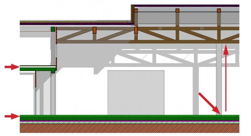
Unfortunately, this modeling technique generally results in somewhat unattractive floor-by-floor views within BIM software or various viewers and checkers—this problem can be addressed, for example, by displaying floors as cross-sections based on their starting and ending elevations. This is handled differently in the various programs; see the following chapter for more on this.
Floor definition
Using the "Floor" tool, you can define both the height and the floor level within a building.
A floor typically begins at the top edge of the lower rough slab and ends at the top edge of the rough slab above it. It is important to ensure that the planes defining the floor are exactly at these heights/edges.
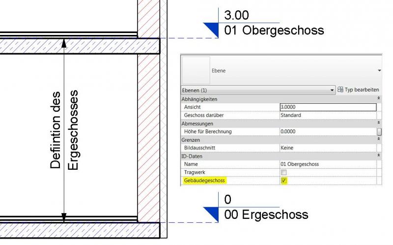
Floor-defining planes differ from the other planes (reference planes) in that the "Building Floor" parameter is enabled.
The number of levels required can vary significantly from project to project.
Key factors include:
- Project complexity
- The service phase you are currently in or that has been commissioned.
- Scope of work
- Probability of planning changes
However, as a minimum requirement, a horizontal plane (floor level) is defined for each known floor.
Each floor level forms the lower boundary of a floor, while the floor level above it forms the upper boundary. The floor designation or floor number is based on the name of the lower floor level.
All objects located either on the lower floor level or between two floor levels are assigned to the respective floor—including intermediate reference planes.
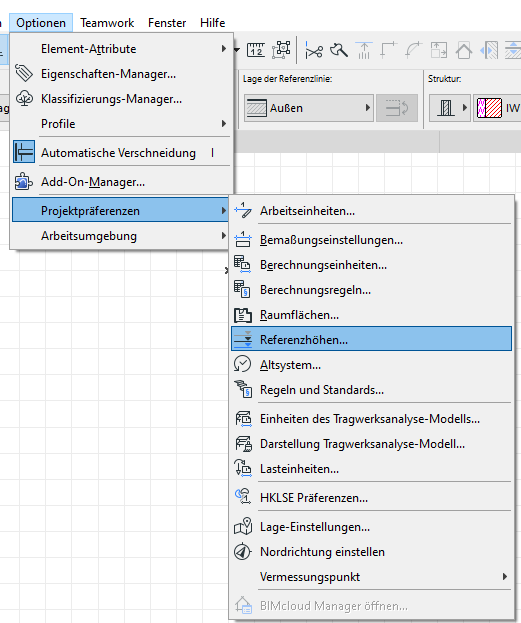
Overview of Projectile Settings
In accordance with ÖNORM A 6241-2, Annex A, the floor level is defined as the top edge of the rough slab (OKRD).
In the project settings and reference heights, the default settings must be configured so that the system’s floor zero = OKRD is consistent.
Use of projectiles
Using the OKRD as the floor level has a correspondingly positive impact on the modeling process, since, for example, walls are automatically positioned correctly when they are connected to the floor above them.
Note: Any issues with automatic elevation dimensioning can be avoided by using the presets for the project plane and reference elevations.
Project Status Overview
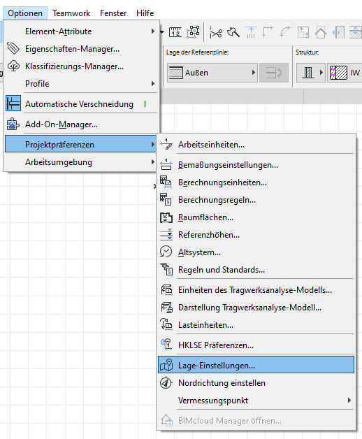
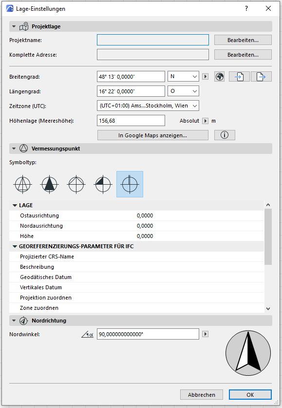
To correctly apply the elevation settings in relation to the actual project location, you must first define the project location. This is where you configure the basic settings for the project’s location, elevation, and orientation. Locating the project in terms of latitude and longitude does not replace the correct positioning of the project model according to Gauss-Krüger coordinates.
Use Project Status
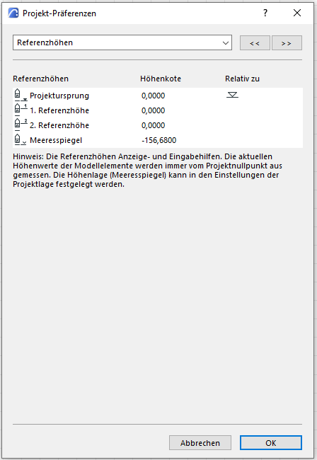
The default elevation setting is closely linked to the reference elevations (and thus to the floor zero definition) and is set to 156.68 m by default—this corresponds to Vienna Zero (= elevation reference point 152.68 m above Adriatic Sea + 4 m elevation value = 156.68 m above the Adriatic Sea).
In reference elevations, the elevation is used as a reference for sea level.
Application: Project Status (Example)
To model correctly in accordance with ÖNORM A 6241-2, Appendix A, the floor zero level refers to the top edge of the rough slab (OKRD)—this greatly simplifies the modeling of building elements with correct intersections. In ARCHICAD, the floor zero is represented by the project origin.
To retrieve the specific location and corresponding elevation values for a project, the following settings must be configured:
Example:
Requirements:
- Project in Vienna (Vienna Zero WN = 156.68 m above sea level)
- Floor level = OKRD
Variables:
- Variable 1: Project elevation above Vienna Zero: e.g., 4.10 m above VN
- Variable 2: Ground floor construction height = e.g., 0.18 m
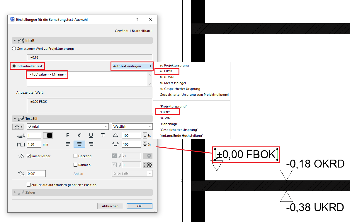
First, in the project preferences/reference elevations, rename the first reference elevation to "above water level" and the second reference elevation to "FBOK".
The new values are then entered—both in the project layer and in the reference elevations.
According to the example, this is done by including the two variables V1 = project elevation relative to Vienna Zero and V2 = ground floor construction height:
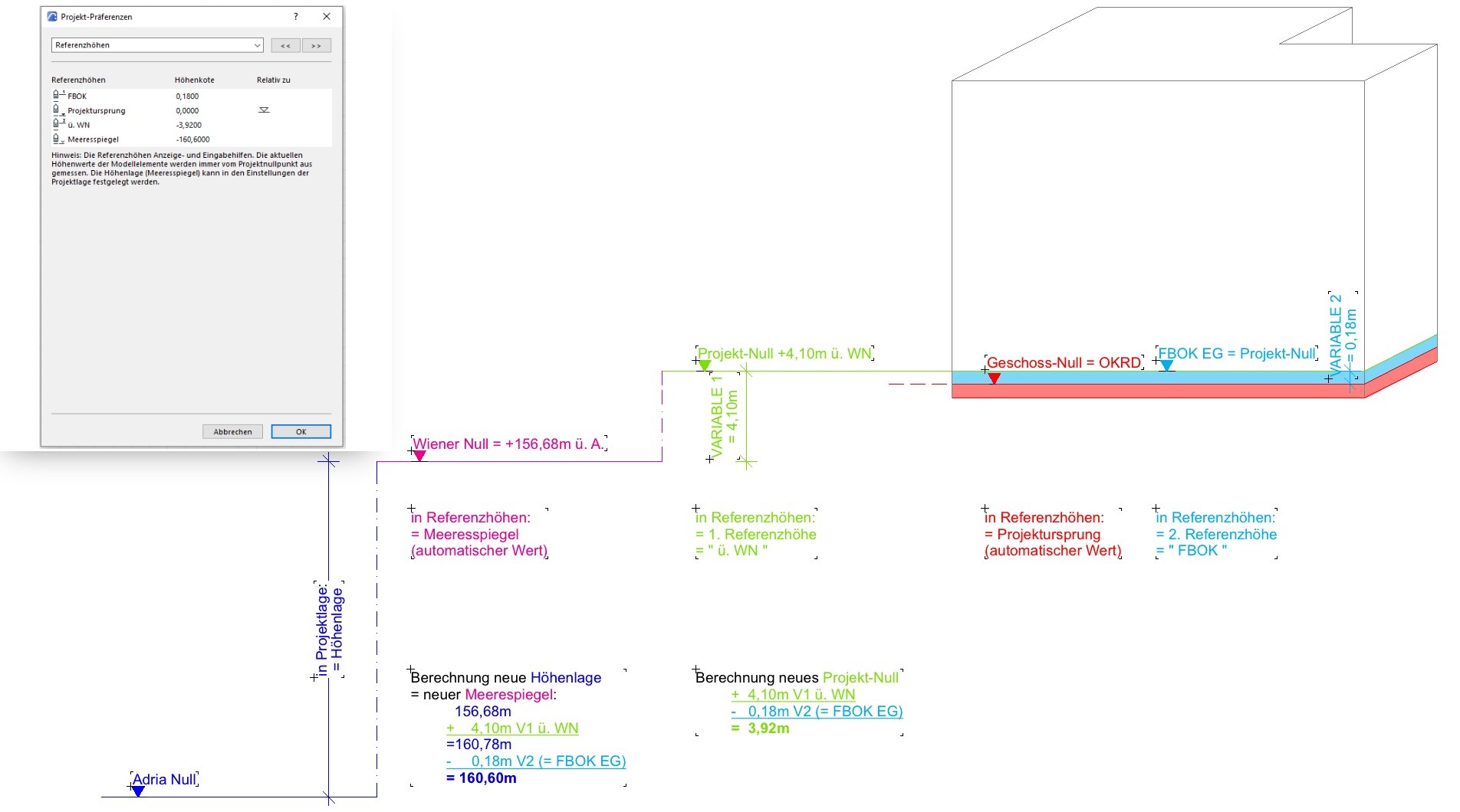
This results in the following representation, for example, in cross-section:
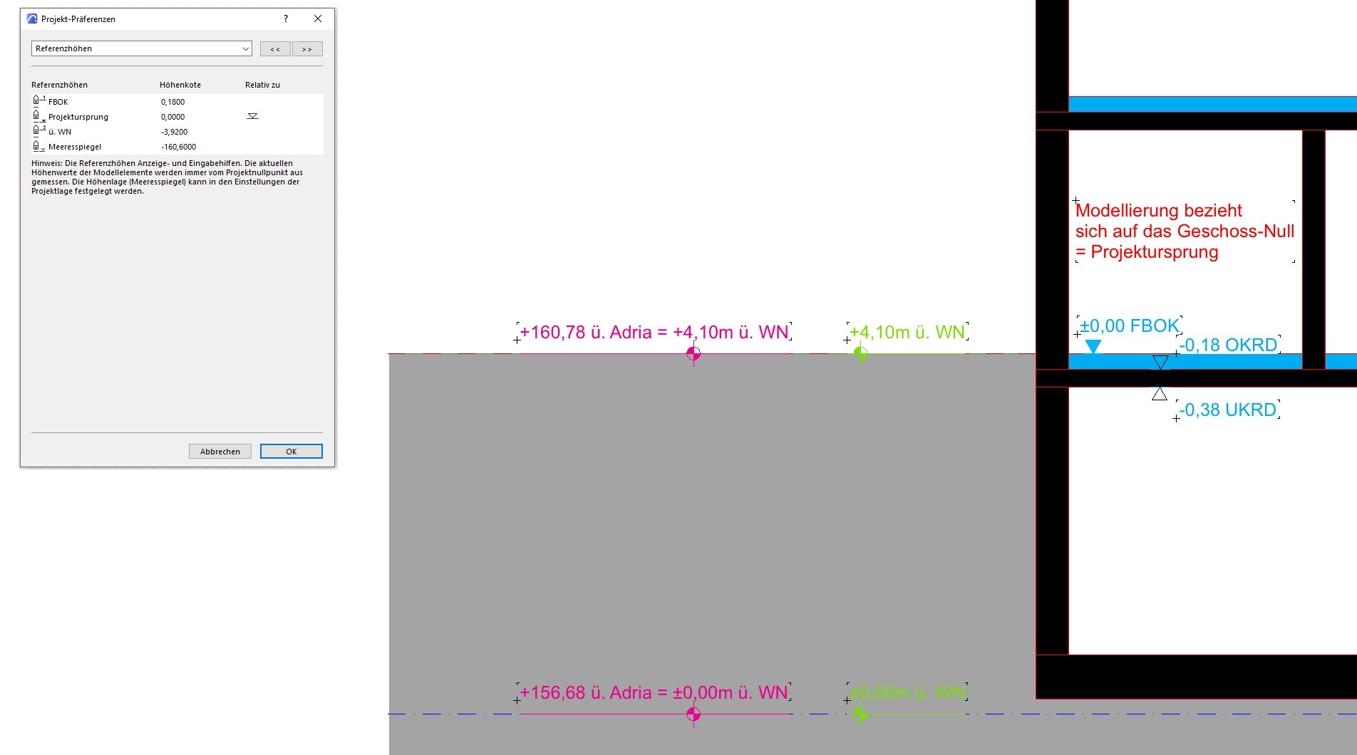
Note: Strictly speaking, the designation of the first reference level should be FBOK EG; however, in order to make the text "FBOK" available on all floors as an automatic text label for all floor-level elevations, the "EG" was omitted. Similarly, the text "above ground level" can be inserted as automatic text.
Model status in the project - Use of the Gauss-Krüger coordinate system
The Gauss-Krüger coordinate system is used to position the project model in its correct location. For a description and tips, see "Positioning in a Cartesian coordinate system."
Regardless of the planning phase, you should always work with floor levels. The benefits this offers—especially when changes are made to the plans during the early stages of the project—more than justify the minimal effort required.
You really come to appreciate floor planes, especially when working with solid models. With the help of these planes, for example, floor areas can be generated from solid models with minimal effort.
- Use the cropping areas

Unfortunately, this content is available only to our Pro users.
If you'd like to read the full article, try the Pro account or become a Pro user.