Precast stairs are a special type of concrete staircase. They offer the advantage of being manufactured in a factory regardless of weather conditions and are immediately capable of bearing full loads after installation. In BIM workflows, they differ from cast-in-place concrete stairs, among other things, due to their geometric notches, which serve as supports on brackets.
This article serves as a supplement to the article "Stairs: General." It is important to review both articles before beginning the modeling process. For additional information on ensuring an error-free modeling process, please also refer to the article "Family Creation."
Search terms: staircase, BFT, single-flight, single-run, double-flight, double-run, concrete staircase, solid staircase
Information on how to handle stairs in the early planning stages is described in the article "Stairs: General Information."
Presentation
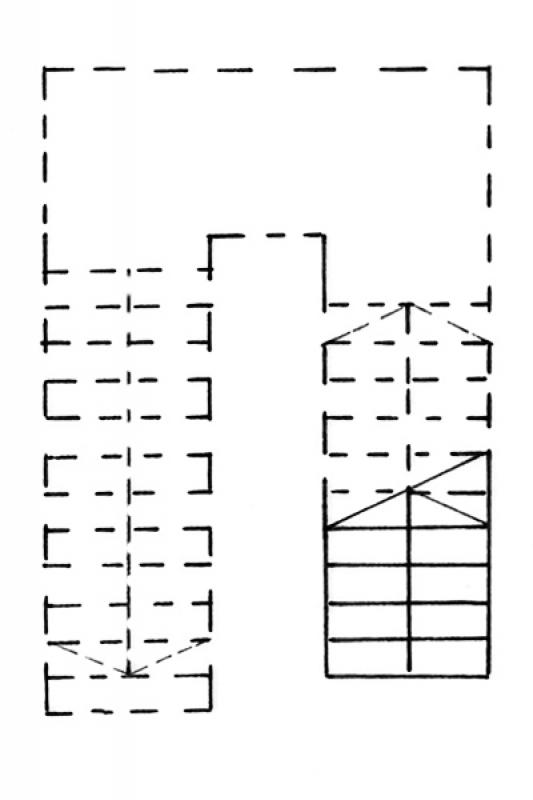
Floor plan
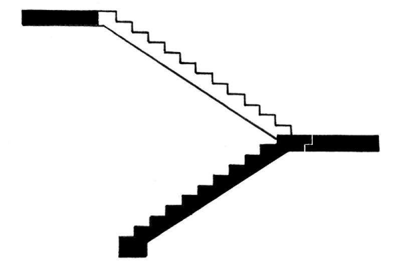
Cross-sectional view
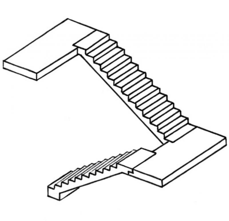
Model representation
Features
Parameters
- Performance
Outline Information
Labeling
- The number of steps and the rise-to-run ratio are indicated by the label "BS_Trep_BFT_Rise-to-Run Ratio".
- Clear passage width is indicated by dimension lines.
Instructions
See the article "Stairs: General Information"
Purchasing prefabricated staircases
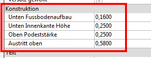
- bottom: FBOK, plus bottom offset (floor covering thickness)
- top: determined by the height of the stairs
Prefabricated stairs are assigned to the 200_Structural Work work area.
Before installing the precast staircase, you should first delete the existing draft staircase (ENT_Staircase....). See also Staircase: Cast-in-place Concrete – Draft
Next, use the "Component -> Place Component" command to place the corresponding precast concrete staircase in Floor Plan 103 using the FBOK reference level.

Prefabricated stairs are created using the following external families:
- Trep_BFT_single-run
- Trep_BFT_single-run_foot
- Trep_BFT_single-flight_foot_intermediate_landing
Family Tax Options
(Exemplarparameter)
Trep_BFT_single-run_foot last appearance and foot
Trep_BFT_single-row first and last appearance
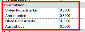
Trep_BFT_single-run_foot_intermediate_landing: Location and length of the intermediate landing,
Foot, final appearance
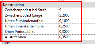
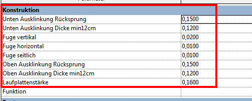
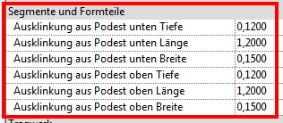
For all three families, in addition to the step height, the notches and joints (lateral, vertical, and horizontal) on the landing can be controlled using type parameters.
Example: Trep_BFT_single-run
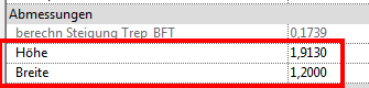
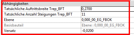
The dimensions of the runs, the offset, the tread length, and the number of risers are entered in the type properties under "Dimensions":
With the Trep_BFT_single-run family, it is possible to add an intermediate platform at the first and last runs. These intermediate platforms can be equipped with additional side notches for suspended BFT runs.
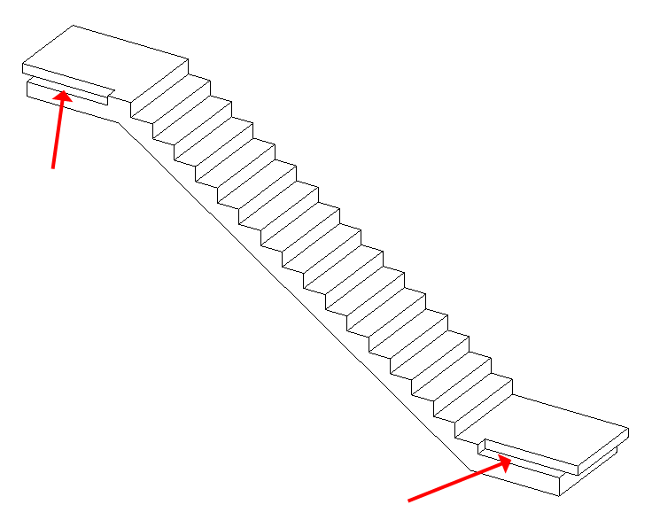
In this case, the staircase is supported at the ends by a wall bracket.
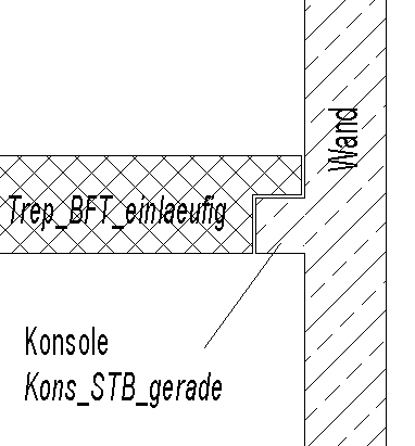
The landings are modeled as load-bearing floor slabs (intermediate and main landings).
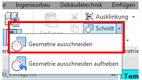
To cut out the notch in the landing, proceed as follows:
Mark the platform you want to work on:
Create the cutout using the "Cut by Geometry" feature:
Notes:
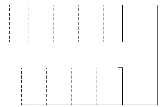
- If the staircases are to be covered with a floor covering, the edges of the BFT stairs must be shown as dashed lines on the floor plan. In this case, the covered staircase also serves as the base for the railing that is yet to be constructed.
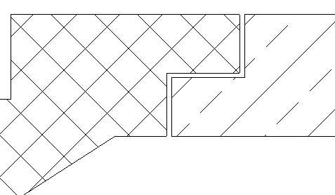
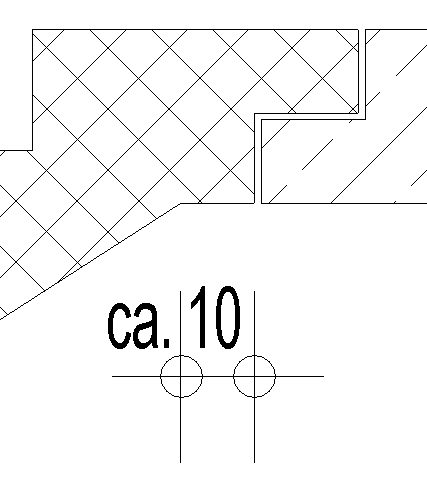
- The upper section of the staircase typically ends with a horizontal edge on the underside. The distance between the bend and the joint can be assumed to be approximately 10 cm.
- The best way to adjust the geometry of BFT stairs is by cutting them to size. (Alignment, position, etc.)
Presentation
Floor plan
Model representation
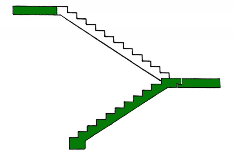
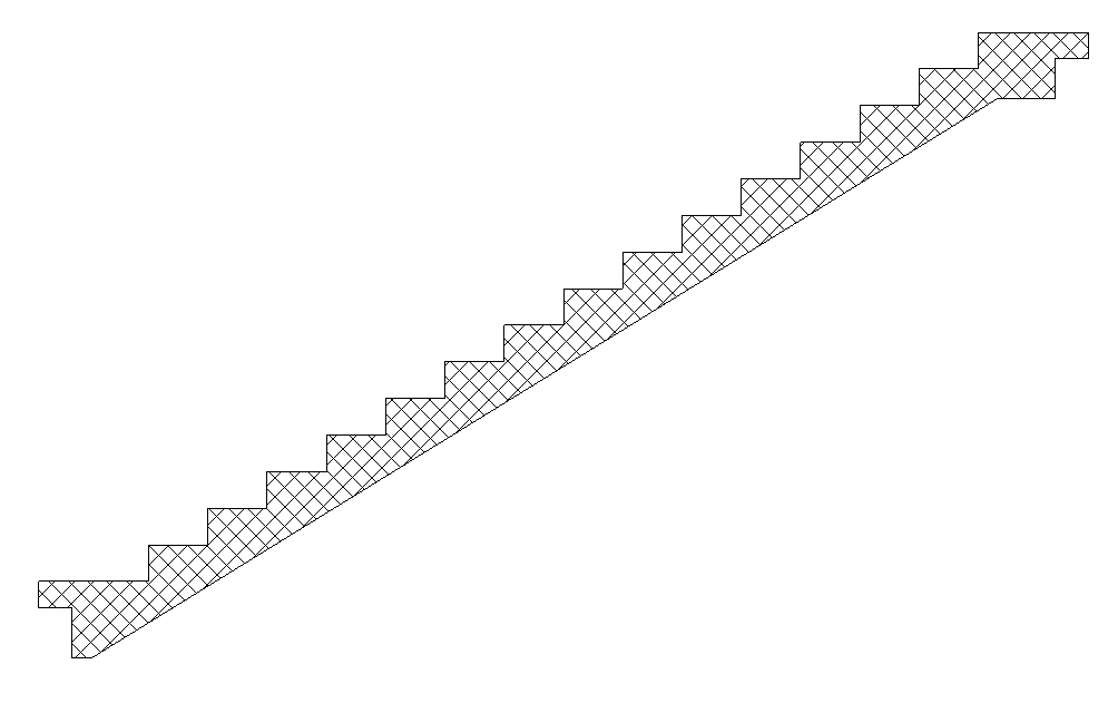
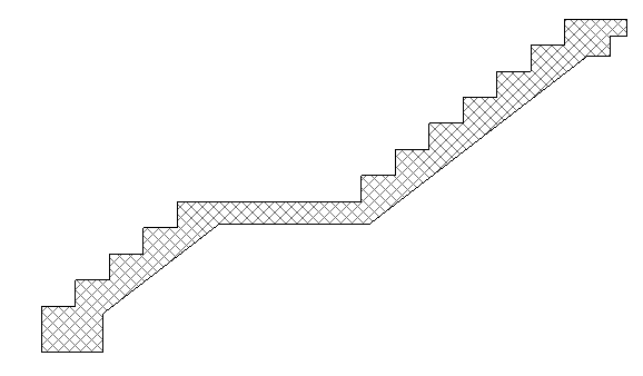
Figure 1
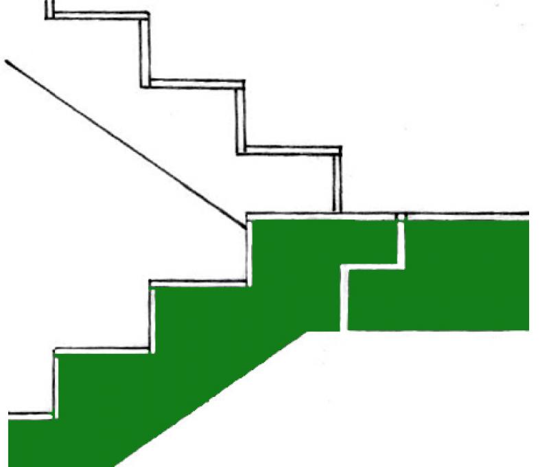
Figure 2
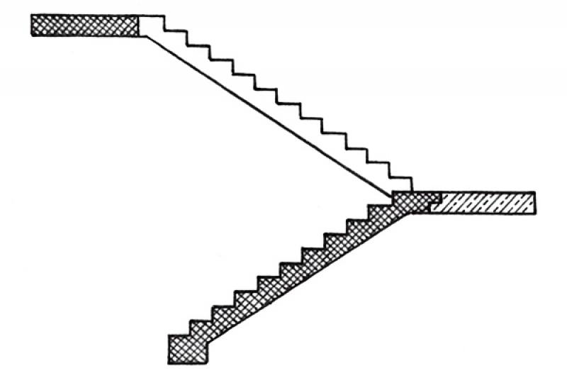
Figure 1
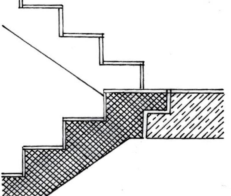
Figure 2
Figure 1
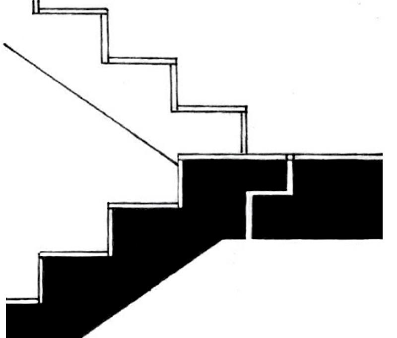
Figure 2
Features
Labeling
- Number of steps and rise-to-run ratio using the label BS_Trep_BFT_Rise-to-Run Ratio
- Clear passage width over dimension chains
Instructions
The attributes are assigned to the staircase's properties so that they can be viewed via labels, among other things.
Presentation
Floor plan
Cross-sectional view
Model representation
Figure 4
Features
Feature
- Number of performances
- Number of inclines
- Step on the running line
- Hollow stair spindle
- Solid stair spindle
- Center-stringer staircase
- Minimum thickness of the stair tread
- Minimum tread depth on the inside
- Status
- Double-stringer staircase
Parameters
- Step on the tread
- Gross volume of the stair run
- Height of inclines
- Length of stair run
- Net volume of stair run
- Overhang
Outline Information
Labeling
All necessary features should be identified using the labels already in use. Additional labels may be required in detail drawings and more detailed sections.
Instructions
Floor plans are created in Revit using views 252 (floor slabs)
Reinforcement detailing is performed in Revit, and the numbering and export of bending schedules are carried out using the "SOFiSTiK Reinforcement Detailing" add-on.
All necessary attributes are assigned to the properties of the objects so that they are available at all times and can be read, for example, via labels
The basic process of modeling a staircase in ARCHICAD remains the same across the various design phases.
A precast staircase without a tread can be created in exactly the same way as an STB staircase: the only difference is that the tread is hidden, and the staircase structure is placed on in-situ concrete. The construction type in the settings dialog must be set to "Precast" in order to configure the staircase accordingly.
The new features and parameters added for this phase must be entered in the appropriate fields of the component's settings dialog.
The description of the settings dialog and the corresponding procedure can be found in an earlier section of this article.
The labeling and dimensioning of components should always be done associatively. Instructions on how to do this in ARCHICAD can be found in the relevant articles.

Unfortunately, this content is available only to our Pro users.
If you'd like to read the full article, try the Pro account or become a Pro user.