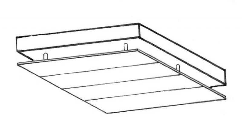
Finished ceilings include all types of suspended ceilings or ceiling cladding, including their substructures. These include, for example, traditional grid ceilings, cleanroom and hygienic ceilings, as well as fire-rated ceilings. Unlike structural floor slabs, which always consist of single layers, finished ceilings can also be multi-layered. It is not necessary to model each individual layer separately.
During this phase, the false ceiling is installed to serve as a placeholder for any subsequent installations. This allows for the reservation of zones, for example, for building services, which often develop their main routing plans in conceptual drawings during this phase. (See Conceptual Modeling)
Presentation
Plan view
Model representation
Features
In this phase, the component is placed for the first time, thereby acquiring its geometric features.
Feature
- Status
- Supporting element
Parameters
- Gross area
- Gross volume
- Nominal ceiling thickness
- Net ceiling area
- Net volume
- Perimeter of ceiling
Outline Information
- Exterior element
- Element in contact with the ground
- Room-enclosing element
Labeling
It is not necessary to label the exposed ceiling or suspended ceiling at this stage.
Instructions
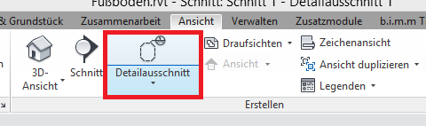
Sloped ceilings are modeled using the Ceiling tool in the Architecture tab.
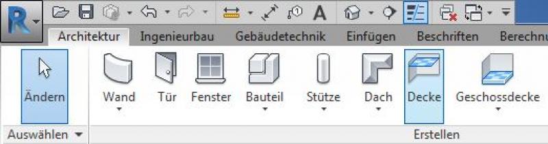
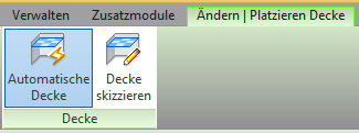
Sloped ceilings can be created either automatically within an enclosing geometry using the "Automatic Ceiling" command, or manually using the "Sketch Ceiling" command.
Ceilings have their height reference point on the underside, which means they are constructed from the bottom up. It is recommended that these ceilings always be modeled on a separate layer. The abbreviation ADUK (for "AbgehängteDeckenUnterKante," or "Suspended Ceiling Lower Edge") is recommended as the layer name.
The basic modeling of a sloped ceiling or ceiling cladding in ARCHICAD does not differ across the various design phases, nor does it differ from the modeling of other ceiling types.
Detailed instructions for floor slabs can be found under "Floor Slabs."
For ease of use in ARCHICAD, you can select the "Standard (single material)" setting.
For advanced users, it is recommended to always select the "Multi-layer" setting (or the "Complex Profile" for structurally more complex assemblies). The advantage of this is that even at the very beginning of a project, during the study phase when components are represented in a simple (single-color) view, the multi-layer structure allows for very precise control of the components from the start. On the one hand, this defines specific, recurring structural thicknesses; on the other hand, a more precise definition of the structural element regarding its use is established right from the start.
Sharing the data with structural engineers, for example, allows for early communication of the intended structural design. Furthermore, this approach is highly recommended for saving time and optimizing a project: as soon as a structure catalog is available, these temporarily defined multi-layer components can be adapted to match the structure catalog—construction elements that reference this multi-layer component immediately adopt this new structure.
Settings dialog for ceilings
Geometry and Positioning
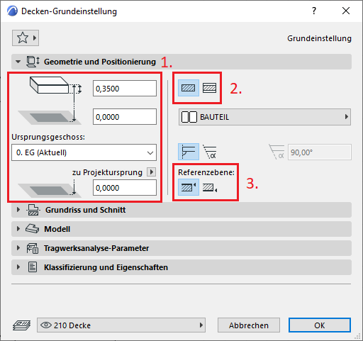
The first basic setting for geometry and positioning concerns the thickness of the slab. This can either be selected manually and assigned a building material, or it can be determined automatically by a multi-layer component.
The second default setting defines the structural method: Single-layer or Multi-layer. It is recommended that you always select the Multi-layer setting. The reason for this is that even at the very beginning of a project, during the study phase when building elements are represented in a simple (single-color) display, the multi-layer structure allows for very precise control of the building element from the start. On the one hand, this defines specific floor layouts (living areas, wet rooms, hallways, etc.), and on the other hand, it allows for a more precise definition of the floor in terms of its use right from the start.
Furthermore, this approach is highly recommended for saving time and optimizing a project: as soon as a structure catalog is available, these temporarily defined multi-layer components can be adjusted accordingly—floor structures that reference this multi-layer component immediately adopt this new structure.
Note: When modeling floors, a distinction is made between different types (according to ÖN A 6241-2, Appendix A): A floor slab is modeled as a single-layer component spanning the entire floor. The floor structure and the suspended ceiling, on the other hand, are modeled as multi-layer components since these structural elements are room-specific. In addition, there are various modeling rules for the different structural elements.
The third default setting defines the position of the reference line. This is specified differently depending on the type of ceiling (floor slab, floor structure, underlayment, suspended ceiling):
Suspended ceiling
With a suspended ceiling, the reference plane is set at the top—on the underside of the rough ceiling. As a result, the clearance automatically increases downward, for example, when the diameters of pipe runs change.
During this phase, colored ceiling layout plans are often created to illustrate the different suspended ceiling heights (or systems). Otherwise, there are no changes to the modeling of the suspended ceilings.
Presentation
Plan view
Model representation
Features
Feature
- Fire compartment-defining element
- Fire resistance class
Parameters
- Tilt (top side)
Outline Information
Labeling
The ceiling system can either be labeled directly using ceiling labeling families, or the ceiling systems can be displayed in color using filters, with the colors explained in a legend.
To label the ceiling system, use appropriate labeling that clearly indicates the desired ceiling system parameters.
The basic modeling of a sloped ceiling in ARCHICAD does not differ across the various design phases, nor does it differ from the modeling of other ceiling types.
The new features and parameters added for this phase must be entered in the appropriate fields in the component's settings dialog.
The description of the settings dialog and the corresponding procedure can be found in an earlier section of this article.
The labeling and dimensioning of the component should always be done associatively. Instructions on how to do this in ARCHICAD can be found in the relevant articles.
Instructions
Color-coded overview maps
Once the slope maps have been created, colored overview maps can be generated very quickly using filters, for example.
This method uses filters based on the distinguishing features of the slope surfaces. When the filters are enabled in a view's "Graphics Display Options," the filtered elements are colored accordingly.
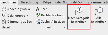
Labeling
In the Label tab, you can label individual slabs using the Label by Category command.
Alternatively, you can use the "Label All" command, which labels all objects in a selected category at once.
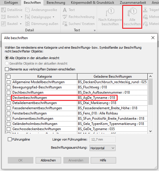
First, select the desired label family from the "Ceiling Labeling" menu and close the menu by clicking "OK." Then, select a suspended ceiling, which will label all suspended ceilings in this view at once.
The basic modeling of a sloped ceiling in ARCHICAD does not differ across the various design phases, nor does it differ from the modeling of other ceiling types.
The new features and parameters added for this phase must be entered in the appropriate fields of the component's settings dialog.
The description of the settings dialog and the corresponding procedure can be found in an earlier section of this article.
The labeling and dimensioning of the component should always be done associatively. Instructions on how to do this in ARCHICAD can be found in the relevant articles.
During the design phase, the floor structure of the floor system must be illustrated. Existing floor plans are often supplemented with additional information, or the floor systems are distinguished in even greater detail.
Presentation
Plan view
Model representation
Features
Feature
- Component activation
- Fire performance
- Sound insulation class
- Impact sound reduction index
- U-value
Parameters
- Gross ceiling area
- Net area of ceiling cladding
Outline Information
Labeling
The labeling and dimensioning of the component should always be done associatively. Instructions on how to do this in ARCHICAD can be found in the relevant articles.
Instructions
Starting in the design phase, specifications regarding ceiling surfaces are typically required for rooms as well.
The specifications from the building component (e.g., regarding the material) and the textual description in the room must be checked for consistency. This check is usually performed manually across different software applications.
In many cases, the existing color floor plans can be used as is. These are simply updated with the additions or graphic adjustments required by the authorities.
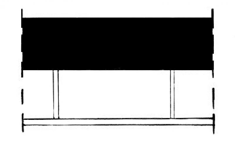
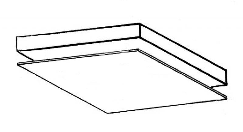
Presentation
Cross-sectional view
![Plandarstellung_2[1].jpg](/media/7D4D6DB8BA0DFB1913CF79633B03DF04/plandarstellung_2[1].jpg)
![Plandarstellung[1].jpg](/media/E7ABD50453F3F4741F695E9324E09538/plandarstellung[1].jpg)
![Plandarstellung_1[1].jpg](/media/EABB2CCBB1FBF6B23FECDAFFC153EC57/plandarstellung_1[1].jpg)
Features
Labeling
- Elevation marks in floor plans and sections
- Layer structure or system structure in a section
Instructions
Due to widely varying regulatory requirements, there is no one-size-fits-all solution for this phase. However, there are general guidelines for improving quality and preventing errors:
- View templates should always be used for graphical customizations, rather than making individual adjustments to each drawing.
- For additional information in the drawing content, always use text families instead of plain text.
The superstructures are shown in detail through close-up views.
Detailed design plans typically require so-called ceiling plans, which differ significantly from general ceiling plans in that they contain more detailed information and are drawn to a smaller scale (e.g., 1:50).
Presentation
Cross-sectional view
Model representation
Features
Feature
- Smoke emission class
- Reference
- Drip formation class
- HollowCorePlugging
- Precast slab
Parameters
- Gross weight
- Net weight
- Thickness of the ceiling covering
Labeling
- Cross-sectional view of the layers
- Depending on the system, information on the direction of installation
- Depending on the system, grid specifications
- The labeling in the ceiling plans is done using the room stamp
Instructions
Ceiling structures are defined using detailed cross-sections. This ensures consistency with the modeled ceilings.
The basic modeling of a sloped ceiling in ARCHICAD does not differ across the various design phases, nor does it differ from the modeling of other ceiling types.
The new features and parameters for this phase must be added in the appropriate sections of the component's settings dialog.
The description of the settings dialog and the corresponding procedure can be found in an earlier section of this article.
The labeling and dimensioning of the component should always be done associatively. Instructions on how to do this in ARCHICAD can be found in the relevant articles.
The superstructures are shown in detailed cross-sections.
Selection
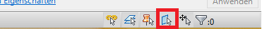
To select ceilings more quickly, you can temporarily enable "Select Elements by Area." This Revit command is located in the lower-right corner.
Base ceiling / Ceiling system
If you start by modeling with the Basic Ceiling family and later switch to the Ceiling System family, the labels—such as elevation marks—will be lost in the views. For this reason, we recommend using only types from the Ceiling System family. As a general rule, you should avoid using Basic Ceiling types.
For suspended ceilings, it is recommended to use the "horizontal air gap" material for the layer in the space between the floor slab and the suspended ceiling structure within a multi-layer component—this serves as an auxiliary layer for clash detection, or determining a sufficient clearance for the suspended ceiling in verification software such as Solibri Model Checker.

Unfortunately, this content is available only to our Pro users.
If you'd like to read the full article, try the Pro account or become a Pro user.