A foundation is part of the overall structural foundation of a building. Foundations are generally classified as slab, wall, or individual foundations. In certain situations, pile foundations are also used. Depending on the software, foundations are handled differently—Revit, for example, offers its own family categories, while in ArchiCAD, for instance, you primarily work with the slab, beam, and column tools and, if necessary, also with morphs.
Like all load-bearing components of a building, the foundation serves as an interface between architecture and structural engineering. If a model-based data transfer to structural analysis software is planned, it may be necessary to use specific modeling methods tailored to the particular software configuration.
Keywords: Foundation, Footing, Frost skirt, Slab, Slabs, Trough, Base, Substructure
During this phase, the foundations are laid for the first time. It is not yet necessary to specify the materials (building materials).
Presentation
Figure 1
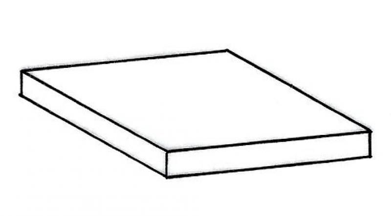
Figure 2
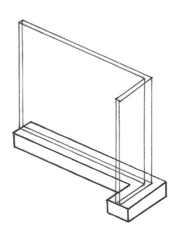
Figure 3
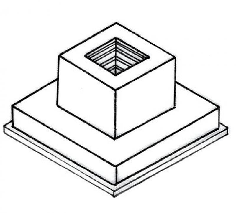
Figure 4
Features
The component is placed for the first time and automatically assigned geometric features.
Characteristic
- Supporting element
Parameters
Outline Information
Labeling
At this stage, the component is not yet labeled in the plan views.
Instructions
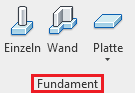
Revit distinguishes between the following types of foundations:
- Individual foundations
- Wall foundations
- Slab foundations
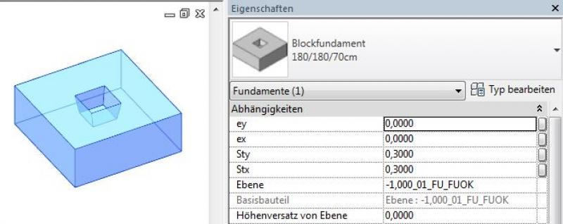
Individual foundations
Individual foundations are created using the command >Civil Engineering >Foundation >Single or, alternatively, >Architecture >Component, and are classified as external families that must be loaded into the project from Revit Content before placement. For new foundation families, the family template >M_Foundation can be used. The size of the foundation is set via >Edit Type and the corresponding type parameters:
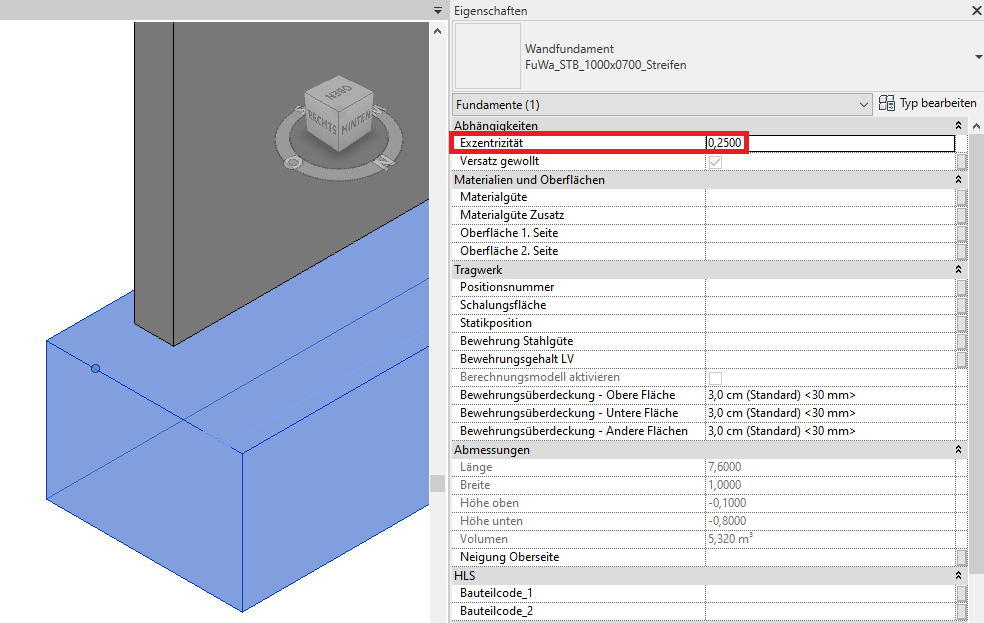
Wall foundations
Wall foundations are created using the command >Civil Engineering >Foundation >Wall; they require a wall as a base for placement in the model (select wall) and belong to the Foundation/Wall Foundation system family. A foundation is limited to the wall it supports. When the wall is moved, the foundation is also moved. Additional wall foundation cross-section types can be created using >Edit Type, >Duplicate, and by adjusting the corresponding type parameters:
If the wall foundation or strip foundation is to be placed asymmetrically beneath a wall rather than centrally (with different lateral foundation overhangs), the >Eccentricity parameter in the Properties window should be set accordingly. In this context, it is recommended to use the corresponding edge of the wall as the baseline:
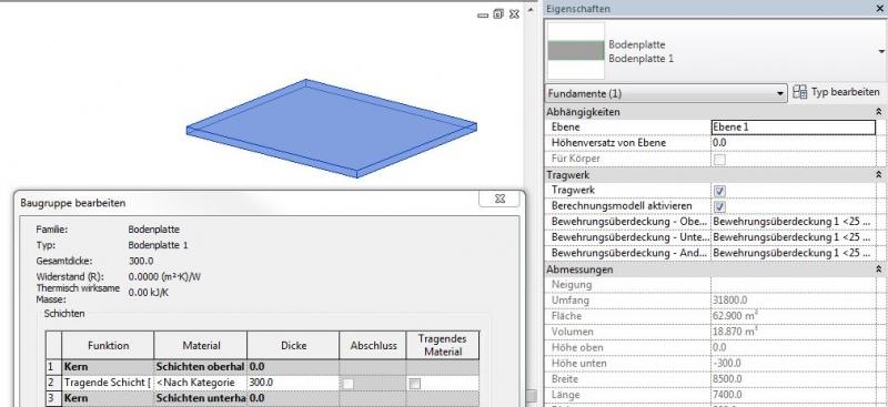
Slab foundations
Slab foundations are created using the command >Civil Engineering >Foundation >Slab and belong to the Foundation/Slab system family. The slab thickness can be set via >Edit Type. Slab foundations are similar to floor slabs in terms of creation, but differ in terms of their structural analysis.
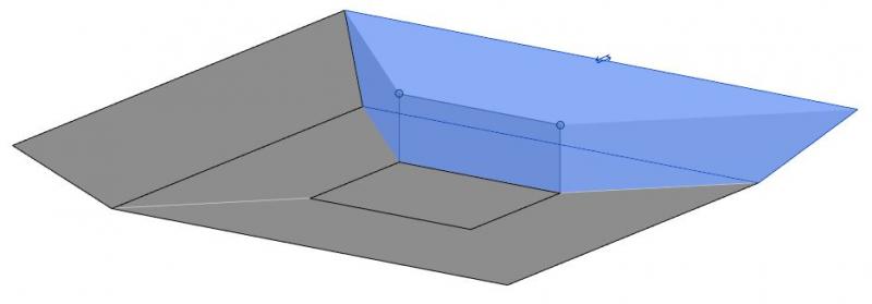
Panel edges
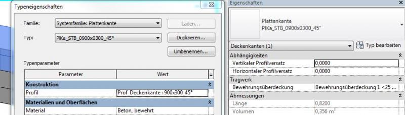
Slab edges are created using the command >Civil Engineering >Foundation >Slab >Floor Slab: Slab Edge and are used for special edges on foundation slabs that need to be sloped, such as in the case of recesses. Different types of slab edges can be created using >Edit Type, >Duplicate, and the assignment of a slab edge profile. The family template file >M_Profile is intended for creating new slab edge profiles:
Overview
In ARCHICAD, foundations are not modeled using a single dedicated tool; instead, different tools are used depending on the type of foundation:
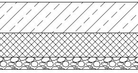
- Floor slab - Modeling using the Floor or Roof tool
- Strip foundation - Modeling using the Beam or Morph tool
- Shoe foundation - Modeling using the Morph tool.
For information on how to use the Morph tool, please refer to Graphisoft's basic documentation in the Help Center.
Building elements classified as foundations do not generally define the space and serve a load-bearing function; they are therefore defined as secondary building elements.
Depending on the type of modeling (the tool used), the tool specifications or the requirements of ÖNORM A 6241-2, Annex A, should be followed.
Consequently, in the settings, the element classification is the first definition in the Categories and Properties section—see also Classification. Selecting the "Foundation" classification ensures that only those properties are displayed in the lower field area that are available for this classification according to IFC attributes.
The three properties that also serve a specific function within ARCHICAD are Structural Function, Location, and Renovation Status—these affect either the structural representation method, the envelope function (in other programs), or the renovation filter. All other attributes must be selected individually or determined in accordance with the project’s organizational guidelines (e.g., project manual or organizational manual).
During this phase, the structural engineering team assesses the load-bearing capacity of the foundations and, based on that assessment, selects the appropriate material (building material).
It is not yet necessary to model the slope of foundation slabs at this stage. However, if a graphical representation is required, this can be done using 2D elements in the floor plan and section views.
Presentation
Figure 1
Figure 2
Figure 3
Figure 4
Features
Feature
- Fire resistance class
- Status
Parameters
- Outer diameter of deep foundation
- Base area of deep foundation
- Lateral surface area of deep foundation
- Slope of deep foundation
- Volume of deep foundation
- Net volume of deep foundation
Outline Information
Labeling
In this phase, foundations are not yet labeled in plan views.
Instructions
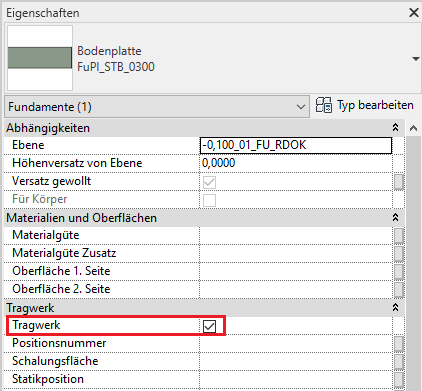
Foundations are load-bearing elements and should always be marked as load-bearing in the Properties window (Parameter: Structural System):
In this phase, the slope of the foundation slabs is indicated only as a label using a 2D detail element.
The basic process of modeling a foundation in ARCHICAD remains the same across the various design phases.
The new features and parameters for this phase must be added in the appropriate sections of the component's settings dialog.
The description of the settings dialog and the corresponding procedure can be found in an earlier section of this article.
The labeling and dimensioning of the component should always be done associatively. Instructions on how to do this in ARCHICAD can be found in the relevant articles.
In this phase, the foundation data is supplemented with structural engineering information. In addition, the foundation slab is given a defined configuration, including a slope. By this phase at the latest, any superstructures—such as floor slabs—should be created as separate elements (see Hybrid Modeling).
Presentation
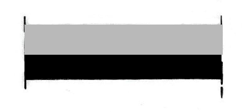
Figure 1
Figure 2
Figure 3
Figure 4
Features
Feature
- Type of foundation
- Ground contact element
- Reference
Parameters
- Wide foundation
- Gross volume of foundation
- Thickness of foundation
- Total foundation surface area
- Height of foundation
- Length of foundation
- Perimeter of foundation
- Cross-sectional area of foundation
Outline Information
Labeling
During this phase, foundations are only labeled on the structural engineering drawings:
- Load diagram: Load application
- Layout plan: Position
- Architecture: Labeling of the top and bottom (foundation slabs)
Labeling for foundations can be obtained from Revit Content.
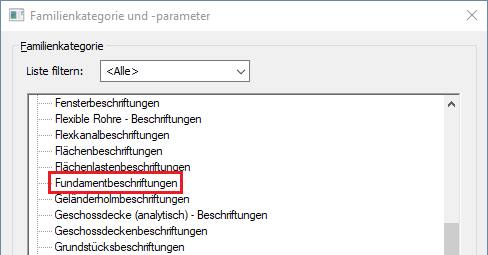
New labels can be created using the label family template >M_General Label. In the new family, the category should be changed to "Foundation Labels" using the >Family Category and Parameters command:
The labeling and dimensioning of the component should always be done associatively. Instructions on how to do this in ARCHICAD can be found in the relevant articles.
Instructions
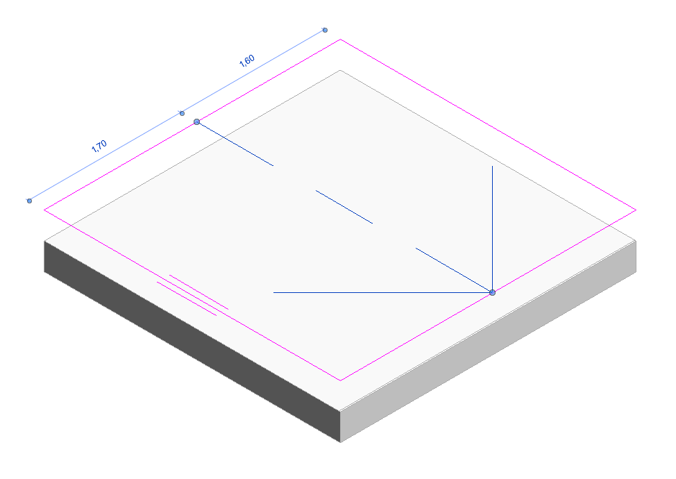
Creating a slope in a floor slab:
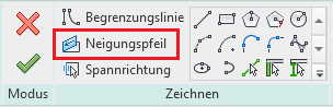
- A one-sided slope on the foundation slabs is created using the >Slope Arrow: Instructions on how to do this can be found here: Creating a sloped surface using the Slope Arrow
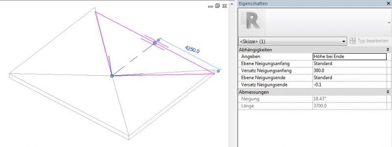
- A floor slab with multiple slopes (such as a rectangular room with four sections and drainage toward the center) can be created by dividing the slab into separate sections and using the Slope Arrow tool. Reason: Editing using shape handles is not available for the Foundations/Floor Slabs category!
Despite this limitation, the following applies:
- A foundation slab should not be treated as a floor slab because it is calculated differently from a structural standpoint and because it will not be processed correctly by tendering software (e.g., ITWO).
- Foundations are always load-bearing
The basic process of modeling a foundation in ARCHICAD remains the same across the various design phases.
The new features and parameters added for this phase must be entered in the appropriate fields in the component's settings dialog.
The description of the settings dialog and the corresponding procedure can be found in an earlier section of this article.
The labeling and dimensioning of the component should always be done associatively. Instructions on how to do this in ARCHICAD can be found in the relevant articles.
At this stage, at the latest, a further distinction is made between the various construction options for structural components. For example, a distinction must be made between cast-in-place and precast foundations.
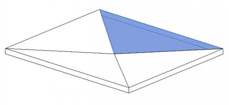
Presentation
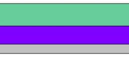
This is where the different countries differ: In Austria, submission drawings are color-coded by building material; this classification is based on the reinforced concrete classification specified in the Vienna Building Code.
Cross-sectional view:

Features
Labeling
During this phase, the architectural team labels the structural components as "ready for approval."
These include:
- Foundation slab thicknesses in cross-sections indicated by elevation marks
- Top and bottom edges of individual and strip foundations in cross-sections using elevation marks
Instructions
To ensure that building materials are displayed in the correct colors in accordance with the Austrian Building Code, a corresponding color scheme should be set to reflect the respective state standards.
Country-specific color settings:
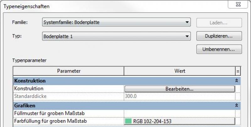
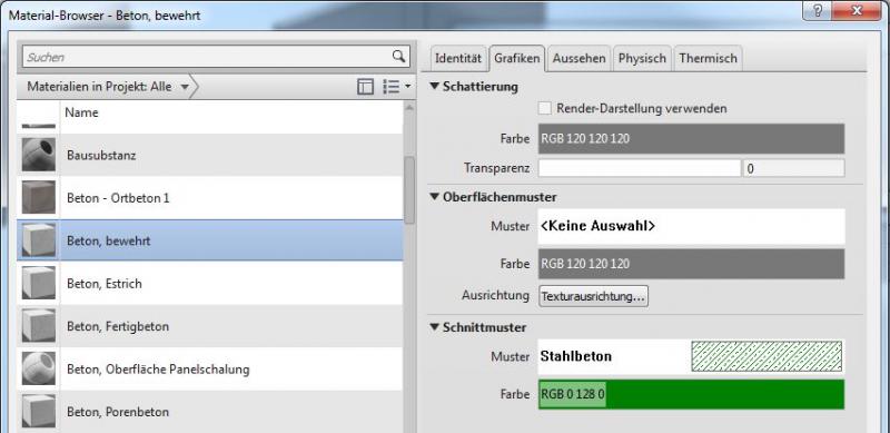
In Revit, the specific color schemes for submission drawings (permit drawings) can be defined in the material or type:
Color type:
Color in the material:
Preparation for the reinforcement
For reinforcement design, all slabs (whether floor slabs or foundation slabs) must be divided according to their concrete pour sections.
The basic process of modeling a foundation in ARCHICAD remains the same across the various design phases.
The new features and parameters added for this phase must be entered in the appropriate fields of the component's settings dialog.
The description of the settings dialog and the corresponding procedure can be found in an earlier section of this article.
The labeling and dimensioning of the component should always be done associatively. Instructions on how to do this in ARCHICAD can be found in the relevant articles.
During this phase, all the information required for the tender process (concrete grade, etc.) is added to the foundation details. In addition, the load-bearing members are reinforced. Depending on the collaboration scenario, this can be done in 3D within the component or in 2D, separate from the model.
Presentation
img_43
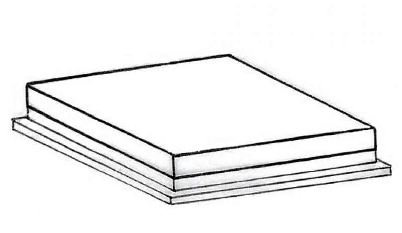
Figure 2
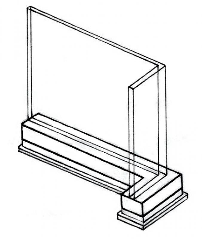
Figure 3
Figure 4
Features
- Precast foundation
- Shoe foundation
- Ground-contact element
Parameters
- Gross weight of foundation
- Slope of top surface of shallow foundation
- Net weight of foundation
- Net volume of foundation
Outline Information
Labeling
In this phase, foundations are fully labeled and dimensioned. In addition, any front edges of foundation slabs, as well as their top and bottom edges, must be labeled in the sections.
Architectural Floor Plan:
- Foundation slabs—bottom, top, and front edges; foundation slab thicknesses
- Dimensioning of all individual and strip foundations
- Dimensioning of all embedded parts
Floor Plan and Structural Design:
- Foundation slabs—bottom, top, and front edges; foundation slab thicknesses
- Dimensioning of all individual and strip foundations
- All information relevant to the building shell (built-in components, openings, etc.)
Instructions
The information regarding the reinforcement to be used in this phase must be provided by the structural engineering team and incorporated into the foundation design.
Ideally, the ceiling should be labeled using a family that retrieves the necessary information from the component's parameters and properties. For instructions on creating new families in the Foundation Labels category, see the guide in this article under the section >Design >Labeling >Revit Workflow
The basic process of modeling a foundation in ARCHICAD remains the same across the various design phases.
The new features and parameters for this phase must be added in the appropriate sections of the component's settings dialog.
The description of the settings dialog and the corresponding procedure can be found in an earlier section of this article.
The labeling and dimensioning of the component should always be done associatively. Instructions on how to do this in ARCHICAD can be found in the relevant articles.

Unfortunately, this content is available only to our Pro users.
If you'd like to read the full article, try the Pro account or become a Pro user.