At this stage, the drainage of outdoor areas is not yet modeled using 3D objects, but rather using 2D surfaces in site plans or floor plans, in order to identify and dimension drainage areas as efficiently as possible.
Presentation
Plan view: Floor plan only, as 3D modeling is not yet being used at this stage.
Features
In this phase, the objects are displayed only in 2D. The required features are created by defining the surfaces. The following features must be defined in this phase:
- General: Name of the area (e.g., infiltration area)
- Generator: Boundary of the area
Labeling
In this phase, the 2D surfaces are labeled.

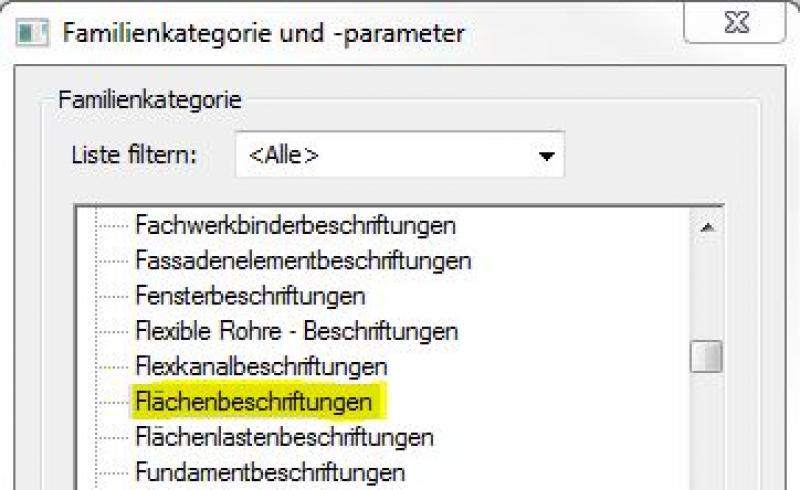
If the desired label does not yet exist, you can create a new label family using the M_General Label template. Be sure to change the category to "Area Labels":
Instructions
In this phase, the drainage for outdoor areas is designed by creating 2D plans.
For more information on creating area plans, see the article "Areas and Zones."
Before creating areas, a special floor plan—known as an area plan—is drawn up, on which the area boundaries are first defined and the areas themselves are then placed.
- Command for creating a floor plan:
>Architecture >Floor Plan >Floor Plan or >View >Top Views >Floor Plan
- Command for creating area boundaries:
>Architecture >Land Use Restrictions

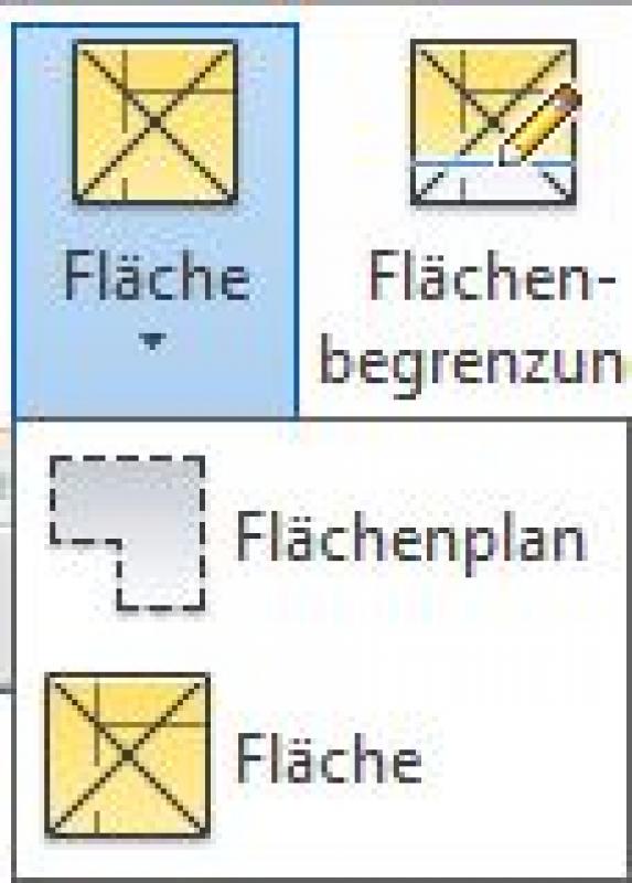
- Command for creating surfaces:
>Architecture >Spaces >Spaces
Overview
For general information on how to use the Room Area tool, the Open Area tool, and the object libraries, please refer to the basic documentation in the Help Center.
This documentation is based on the official template file 01 ARCHICAD 20 Template.tpl from the ARCHICAD 20 AUT version.
The modeling of drainage areas varies depending on the project phase: up to the submission stage, these are defined as areas superimposed on the terrain model; in subsequent phases, the drainage elements are additionally placed as library objects (gutters, sewers, etc.). The Profile Manager function is also used for swales.
A drainage area defined as a room area is treated as a building element, since it is inserted into the model in three dimensions and classified as a documentation element. A building element placed as an object serves as an example for the equipment area, determines a usage assignment for connection points, or defines equipment items; since these are neither structurally relevant nor space-defining, they are defined as Building Element Class II.
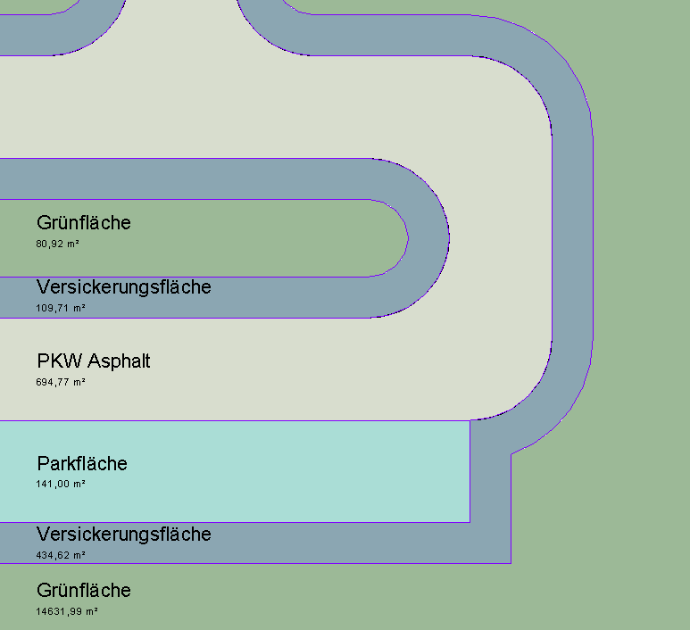
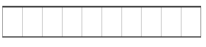
The area allocated for drainage is 80 space stamps:
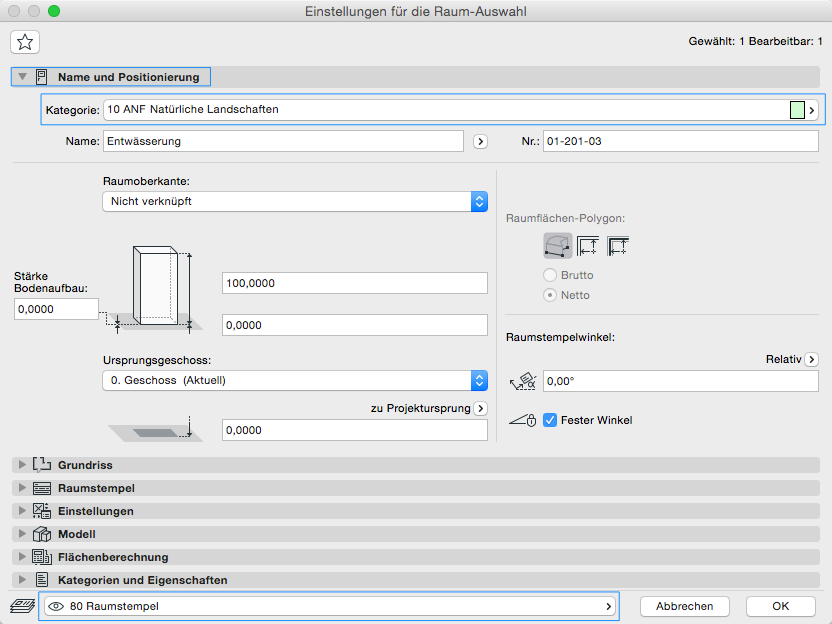
The Room Area tool is used as described in the "Rooms" section. The room category ANF_20_Natural Landscapes is intended for drainage areas.
No further measures will be taken at this stage to address drainage in outdoor areas.
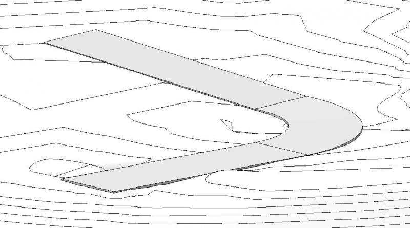
During the design phase, the drainage of outdoor areas is first modeled in 3D and supplemented with elevation and slope data pertaining to roads, parking areas, and the terrain (topography). The primary focus here is, on the one hand, on determining slopes, low points, and high points for the necessary drainage of paved surfaces and, on the other hand, on the resulting terrain adjustments.
Presentation
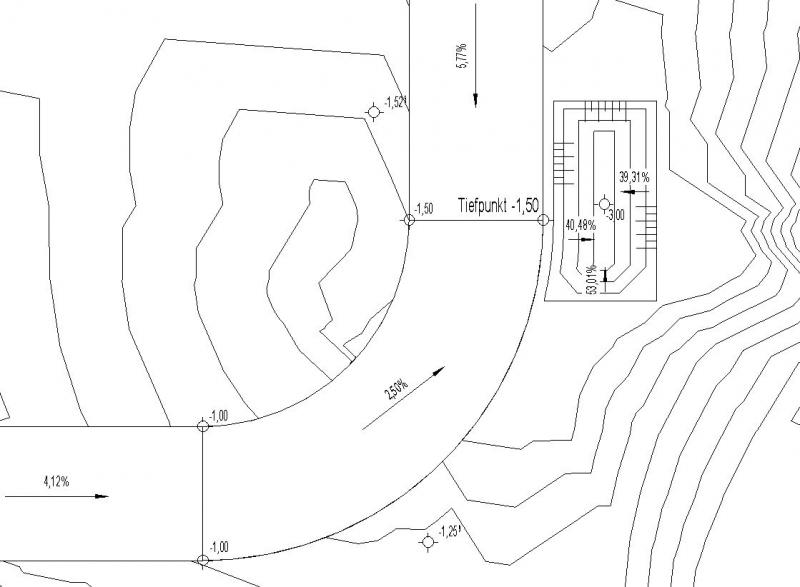
Figure 1
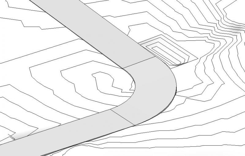
Figure 2
Features
The following features will also be defined during this phase:
- Input parameters: geometry, elevations of the main drainage points, slope
Labeling
In this phase, the main drainage points are assigned elevation coordinates and gradient values (slopes).
In Revit, elevations are created using the >Label >Elevation and Slope commands:
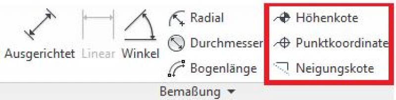
- Drainage points using the command: >Label >Elevation
- Slopes using the command: >Label >Slope
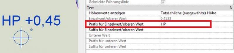
Additional text, such as ... (= elevation point), is entered in the "Prefix for single value/upper value" (elevation marks) or "Prefix" (slope marks) parameter.
Instructions
Elements relevant to drainage—such as roads, parking areas, and sidewalks—as well as the site and its adaptations to the construction process are created during this phase, and their surfaces and edges are adjusted to the planned elevation.
In this phase, the design of the drainage elements to be modeled generally consists of two parts:
- Roads and Parking Areas
- Site modifications / adjustments
Roads and parking areas can be modeled in Revit using floor slabs or created by modifying the terrain. Instructions on how to do this can be found in the article "Roads and Sidewalks." Terrain modifications, such as those for infiltration basins, can be found in the articles Terrain (Topography) and Excavation. A prerequisite for planning these elements is topography based on survey data! Drainage of paved areas in outdoor facilities:
Illustrated using a street as an example.
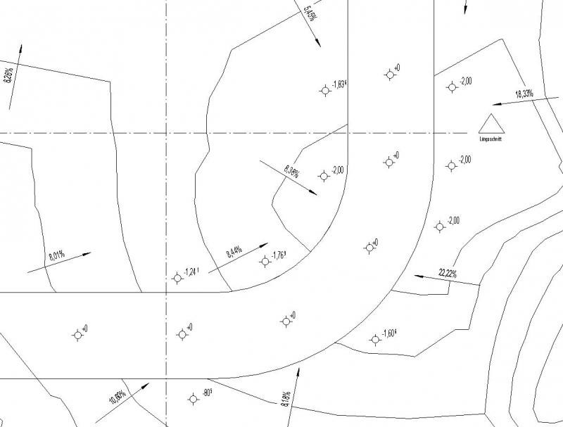
- Step 1: Create the main paved outdoor areas in a floor plan (roads, sidewalks, parking areas, etc.) by first drawing flat floor slabs at a level slightly above ground level. In addition, it is recommended to add elevation and slope contours along the edges of the paved areas to better assess the elevation of the surrounding terrain:
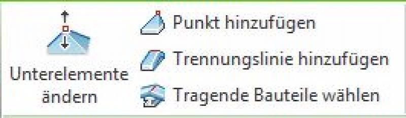
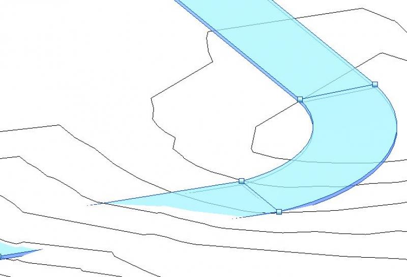
- Step 2: Adjust the key edge points of outdoor areas to the terrain using shape editing commands (e.g., >Modify Subelements). In this example, the endpoints of the individual road sections (straights, curves). This step defines the slope of the paved areas (checking via >Slope Elevations is recommended):
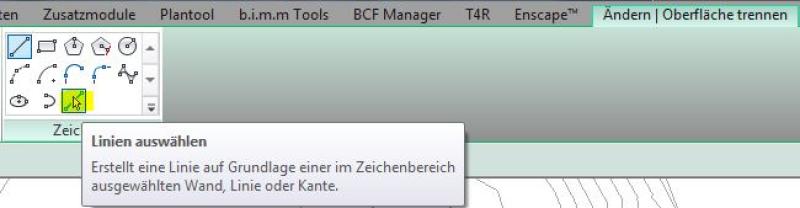
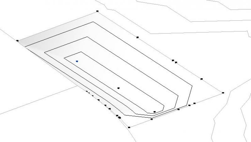
- Step 3: Adjust the terrain by partitioning the area beneath the paved outdoor spaces and correcting the adjacent elevation points. The division is performed using the command >Solid Model & Site >Split Surface (not >Subregion, because this prevents the terrain from being edited at the edge areas). It is recommended to use the drawing tool >Line:
After selecting a portion of the topography, you can use the >Edit Surface command to adjust the elevation of the boundary points relative to the fixed surface:

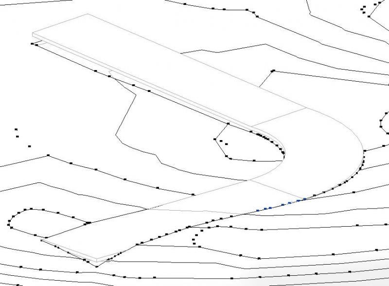
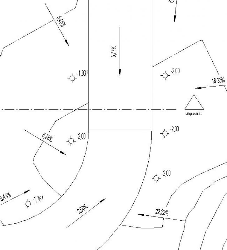
- Result: on the one hand, a road alignment (or other paved surface) adapted to the topography, and on the other hand, a topography adapted to the road alignment (or other paved surface):
Drainage elements on the site:
Illustrated using the example of a septic tank:
When making terrain adjustments, only step 3 of the procedure described above is required:
- Select the section of the septic tank using the command >Solid Model & Property >Split Surface
- Then edit this part of the site using Command > Solid Model & Site > Edit Surface

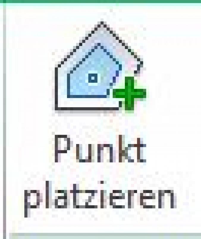
- Add additional terrain points using the command >Body Model & Lot >...
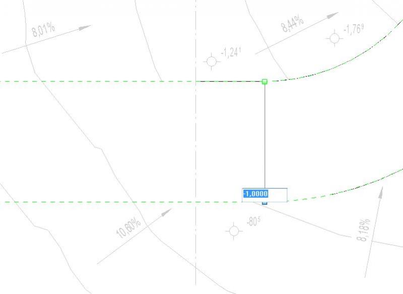
- Change the elevation of the point (in this case, the lowest point) in the Options bar under >View when the point is selected:

For instructions on modeling and dimensioning a terrain model, see Terrain/Topography—these instructions also apply to the creation of a drainage system.
During this phase, the design is further refined using 3D drainage objects (swales, storm drains, etc.).
Presentation
Plan view
Model representation
img 19
img 21
Features
The following characteristics must also be defined during this phase:
- Generated: Elevation of the objects
- Calculating: Areas, slopes
Labeling
The labeling is done in the same way as for low and high points.
- Drainage points using the command: >Label >Elevation
- Slopes using the command: >Label >Slope
Instructions
During this phase, drainage elements (drains, ditches, etc.) are installed.
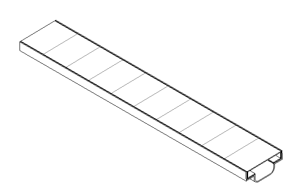
Ditch
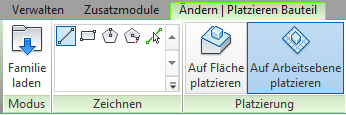
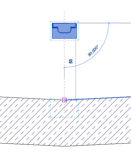
To place infiltration trenches, use the >Architecture >Component command, making sure to select the >Place on Work Plane option in the ribbon.
In a section, the height can be checked and adjusted if necessary. This can be done either using the "Move" function or directly via the "Offset" parameter.
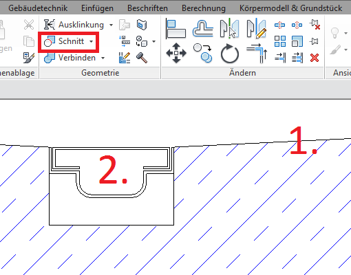
Use the >Modify >Geometry >Cut function to cut the trench out of the base component: First select the floor slab, then the trench.
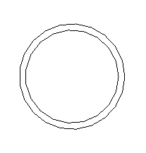
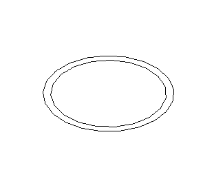
Drain grates
Drains are always installed on a countertop.
Overview
Drainage objects are located on Level 70 (Sewer). Elements created using the Profile Manager are also placed here.
Usage - Profile Manager
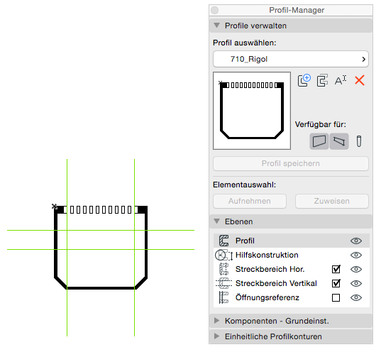
When using the Profile Manager to create a trench, the specifications for the Wall tool’s settings dialogs apply, since a trench profile is modeled using this tool. The definition of a drainage ditch profile varies by manufacturer and is specific to each case; however, the modeling conventions described above also apply here.
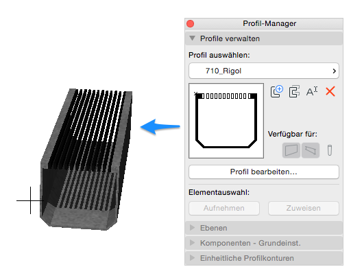
Example: Rigol:
3D rendering:
If you need help creating a complex profile, please refer to Graphisoft's basic documentation in the Help Center.
No further drainage measures are required at this stage.

Unfortunately, this content is available only to our Pro users.
If you'd like to read the full article, try the Pro account or become a Pro user.