In the construction industry, the term "terrain" (also known as topography or relief) refers to the natural surface of the earth—or the surface that has been altered for a construction project—excluding any objects, buildings, or bodies of water located on it.
The surveying of points on a site or on building structures falls under the purview of the engineering surveying department. The three-dimensional representation of the survey data is either provided by the surveyors in an agreed-upon data format or modeled by the architects (based on any available survey data).
In the second scenario, it becomes necessary to use digital survey data as the basis for representing the terrain in BIM projects. This data is typically available in an AutoCAD site plan created by the surveyor or in the form of laser-scan-based point cloud data, which can be transferred into a BIM model for further processing using special methods described below.
Terrain modeling can be viewed as the foundation for further workflows, such as planning excavation work, open-space design, and landscaping.
Search terms: terrain, area, earth, soil, topography, ground, plot, boundary, landscape, contour line, stratum line, elevation, surveyed, topography, geography, geographical
At this stage, terrain is generally not yet modeled.
At this stage, terrain is generally not modeled yet. However, if survey data is available, it may well make sense to begin terrain modeling as described in the "Design" section.
In addition, terrain modeling may be useful at this stage if the geometry is complex (e.g., on sloped terrain) or if visualization in context is desired.
In this phase, the site is typically modeled for the first time. It is not necessarily required to define materials (construction materials) at this stage, but doing so can be quite useful if they are known (e.g., if the soil is standard).
Presentation
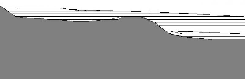
Plan view (cross-section)
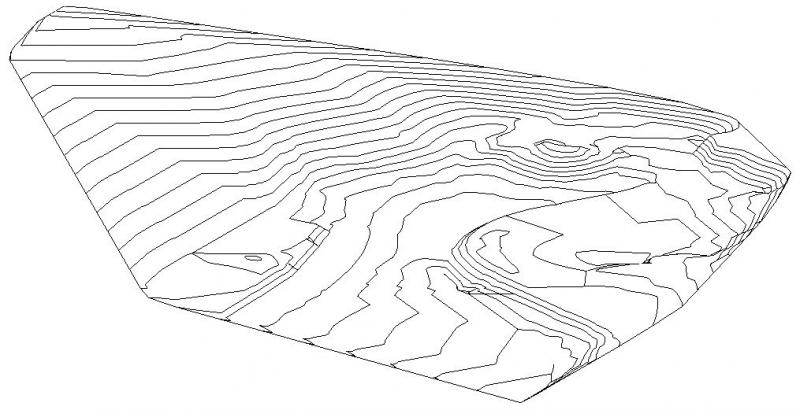
3D model
Features
Feature
Parameters
Outline Information
Labeling
Terrain features are generally not labeled; any labels refer to terrain points or slopes.
In Revit, these labels are created as follows:
- Label a point (location in the Cartesian coordinate system) using the command >Label >Elevation
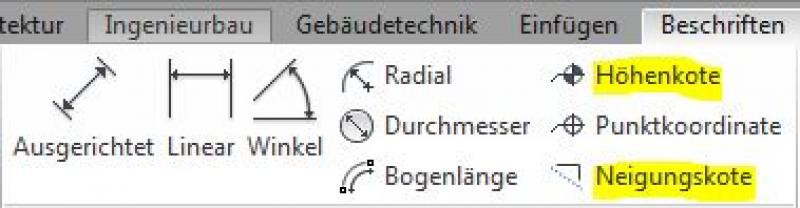
- Label slopes using the command >Label >Slope Elevation
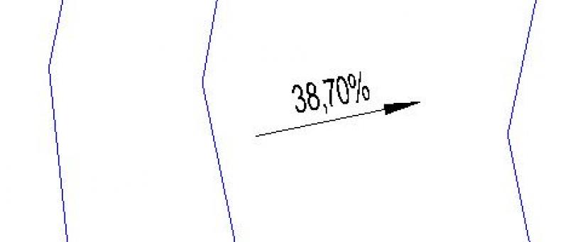
When placing elevation marks on terrain features, always ensure that the Gravity in open spaces is set.
Instructions
In general, terrain modeling is based on survey data, which is typically provided in the following formats:
- 3D Contour Lines in 3D DWG
- CSV files (point files) / CSV files from 2D DWG files
- Text files (point files)
Based on this, there are various methods for automatically creating terrain in Revit:
Create a terrain model from 3D elevation contours in a 3D DWG file
Overview
For general information on how to use the Open Space tool, please refer to the basic documentation provided by Graphisoft in the Help Center.
This documentation is based on the official template file "01 ArchiCAD 25 Template.tpl" from the ArchiCAD 25 AUT version.
Outdoor facilities (topographies) are classified as site geometry (Site).
The level for outdoor facilities is 610 Site:
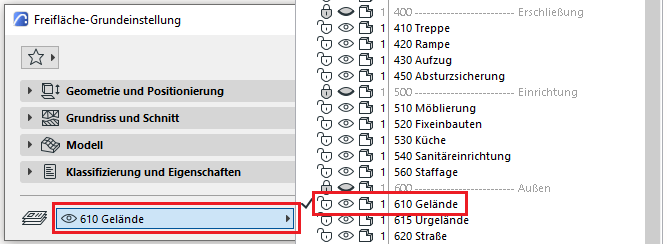
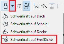
Terrain geometries are created using the Open Space tool.
Geometry and Positioning
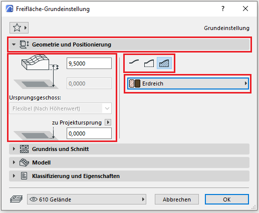
The following geometry methods are available for a terrain: top surface only, with apron, or solid body—you should always use the solid body geometry method, as this is the only way to define and evaluate a volume.
The open space must be modeled at floor level zero (= OKRD, in accordance with ÖNORM A 6241-2, Annex A), just like all other building elements. The (structural) height should be set lower than the last (basement) floor. Since no multi-layer components are available for open spaces, modeling is always performed using a specified building material.
Floor plan and cross-section
Model data can also be displayed using projections in floor plans, elevations, and sections—the following description explains the available options.
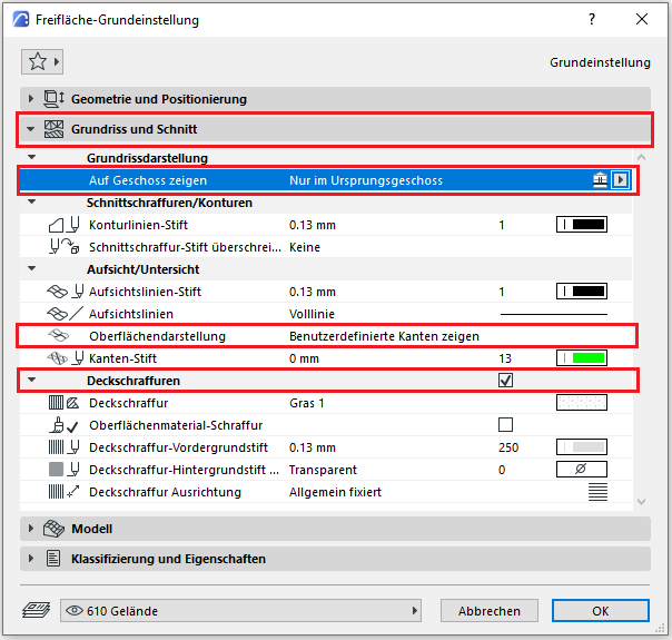
The floor display settings for open spaces should be configured on a project-by-project basis—for example, on sloped sites, the "Only on the base floor" setting may not be sufficient. In such cases, we recommend using a custom setting.
The surface display should be set to "Show custom edges" so that the floor plan view is not cluttered with unnecessary polygon meshes.
Similarly, the colors used for contour lines, section lines, and top view lines—as well as any hatching—can be customized. For special or temporary display changes, you can always use the "Graphical Override Styles" option.
Model
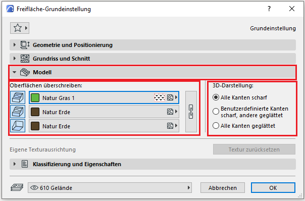
In the Model section, you can override the surface of the building material being used. For example, for the "Natural Soil" building material, you can redefine the top surface of the open area with a "Natural Grass" surface.
The edge sharpness/smoothing option is usually adjusted during the modeling process. "All edges sharp" works very well for the modeling process, while smoothing is typically applied after the terrain is complete to give it a softer appearance.
Classification and Characteristics
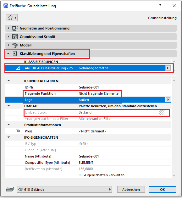
The element classification is the first definition in the Classification and Properties section—see also Classification. When you select the terrain geometry classification, only the features available for that classification are displayed in the lower field area.
The three properties that also serve an additional function within ARCHICAD are Load-Bearing, Location, and Renovation Status—these affect either the structural representation method, the envelope function (in other programs), or the renovation filter. All other attributes must be selected individually or in accordance with the project’s organizational guidelines (e.g., project manual or organizational manual).
Usage - Terrain Creation
A new open space to be created is usually based on the surveyor's base data (which can be 2D, 3D, or laser-scan point clouds). The surveyor’s data is imported into the project via File > Interoperability > Import. This data is usually already provided in accordance with the project’s origin as defined by the Gauss-Krüger system, whose coordinate system should be adopted in the project.
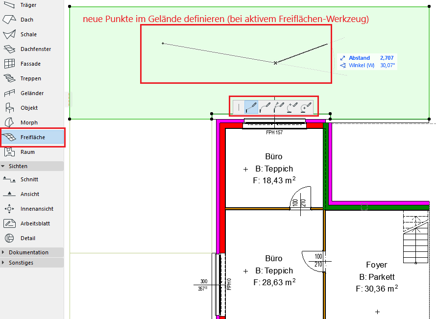
A newly created open area initially consists of a solid body bounded by an outer edge. This open area does not initially have any points at different heights.
To generate new points or terrain lines within the open area, select both the open area and the Open Area tool at the same time—this allows you to insert new individual points, lines, arcs, etc., into the terrain.
To assign a new position on the Z-axis to the individual elevation points in the open space, select them and either enter the values manually (based on the elevation contours in the 2D survey plan) or drag them to a specific elevation in the 3D view (based on the 3D survey plan terrain position).
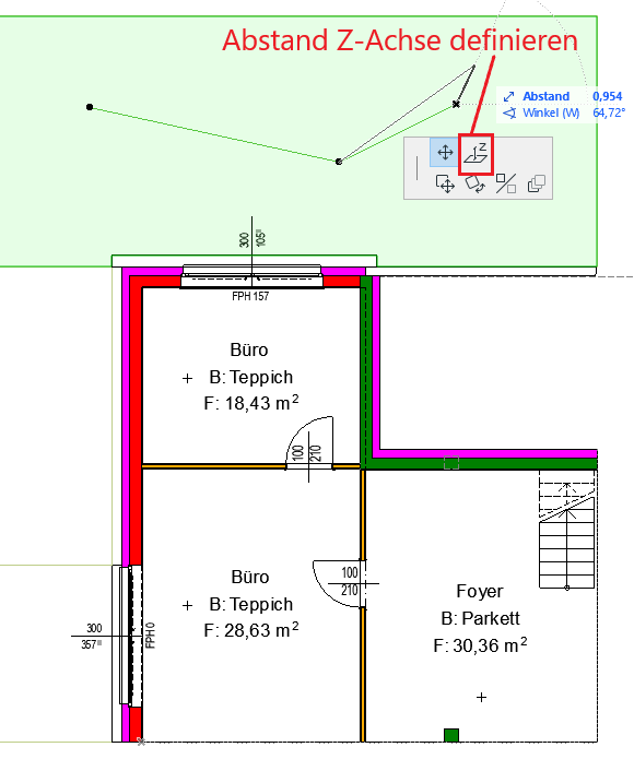
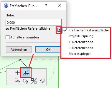
When setting the Z-axis position, always note the reference to which the elevation is being adjusted—since the project origin is located at the top edge of the rough floor, the reference should be set to FBOK (top edge of the ground floor).
Elevation reference lines are therefore displayed automatically, and their appearance can always be customized.
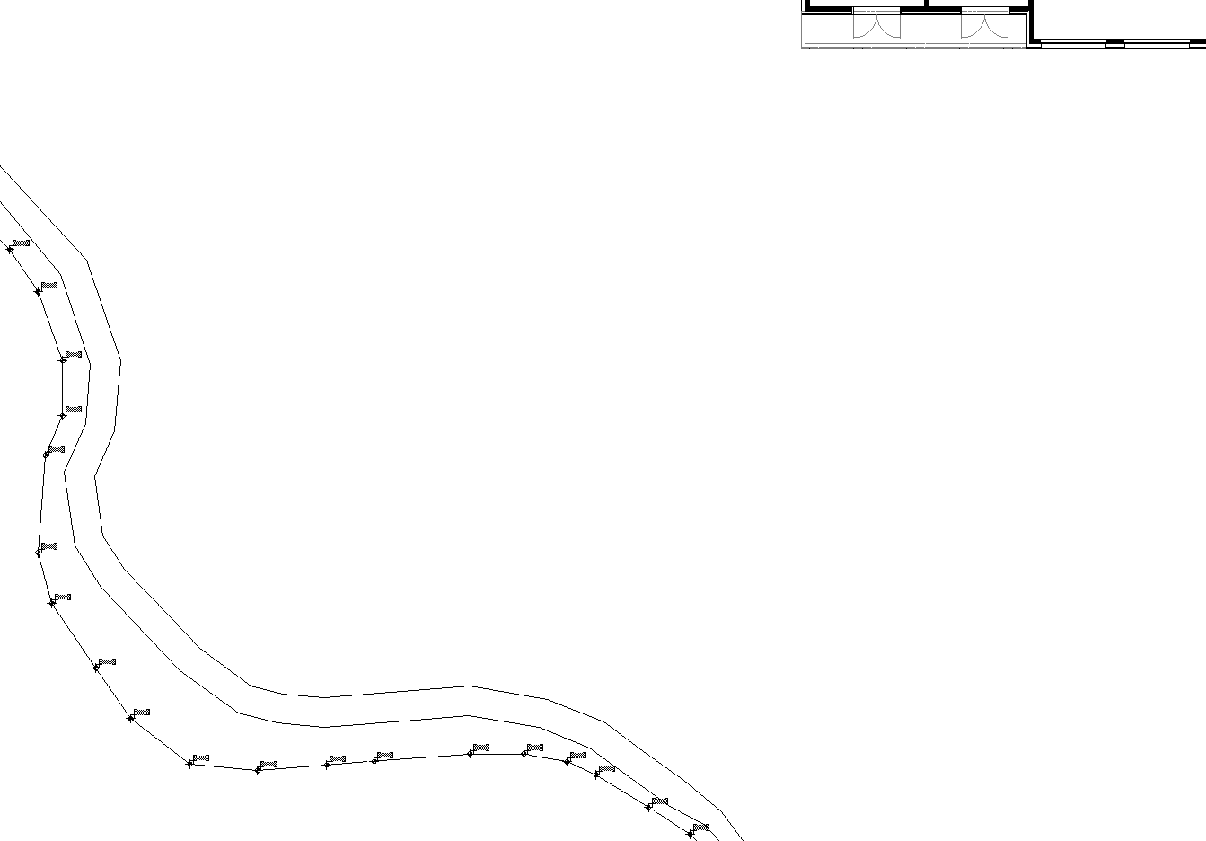
If you have received 2D contour lines from a surveying firm, for example in DWG/DXF format, you can open them in ArchiCAD and prepare them for further use. You should always ensure the project file remains clean; that is, the imported content should not simply be merged with your model. We recommend using a new empty file, importing the contour lines there, and resolving them in that file. The terrain geometry should be created in this file, and once you are finished, copy it into the project file. You can copy the surveyor’s plan as a drawing into the project file, but you should not import it; instead, place it on a defined layer and use it as a reference.
We will show you a simplified workflow for adding new points to the terrain geometry using contour lines.
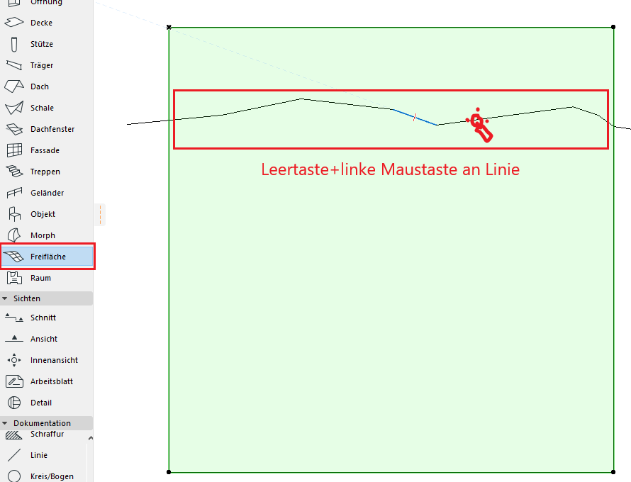
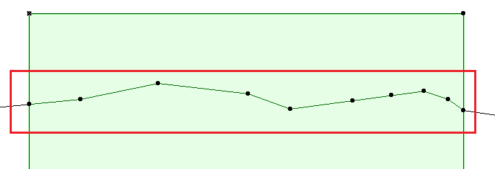
We drew the contour lines as 2D lines and modeled the terrain in the floor plan area using the Open Space tool. Let’s select the terrain and then activate the tool in the tool palette. Hold down the spacebar and left-click on the contour line.
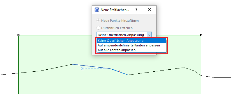
A dialog box will appear where you can specify how the new points should be added to the open area. We recommend selecting the "No surface adjustment" option to avoid unwanted changes in elevation and the creation of additional control points.
To explain: if an open-area element already has numerous interior points whose heights have been adjusted, the newly added points can connect to all of them and corrupt our geometry.
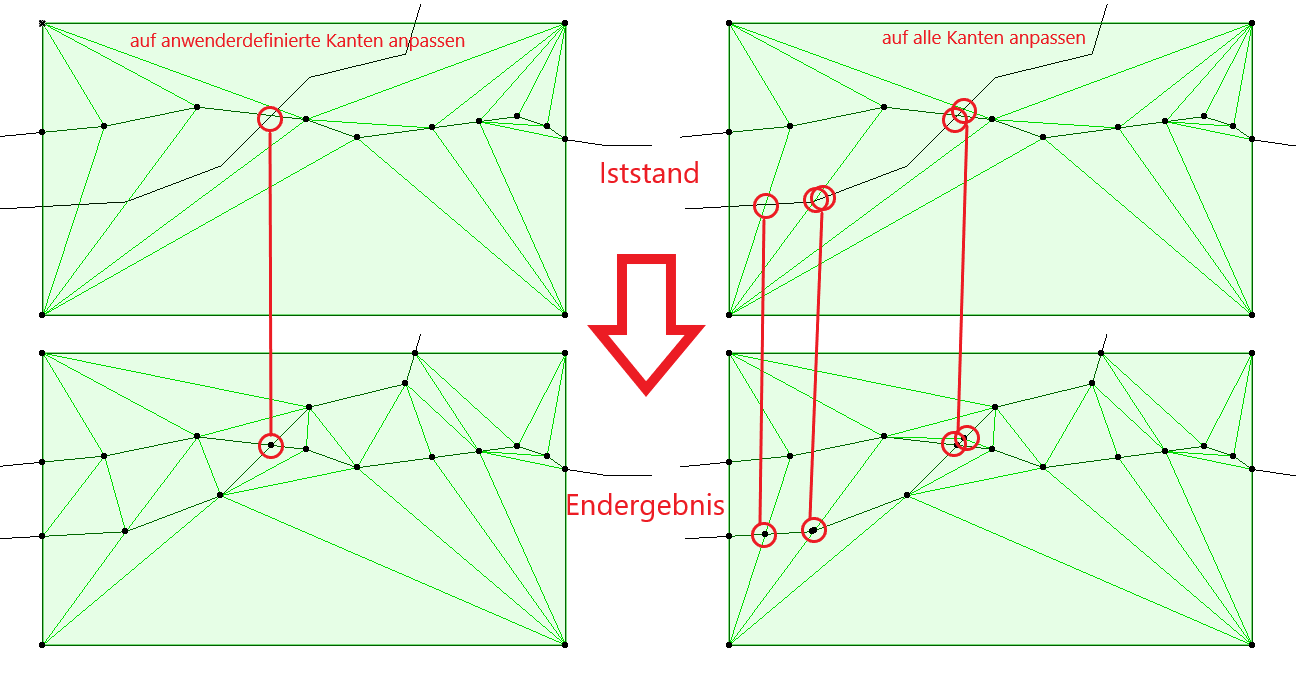
If you select the "Align to user-defined edges" option, only the lines you have created will intersect with each other. If you select the "Align to all edges" option, the polygon edges of the open area will intersect with the new line.
Site Surveying
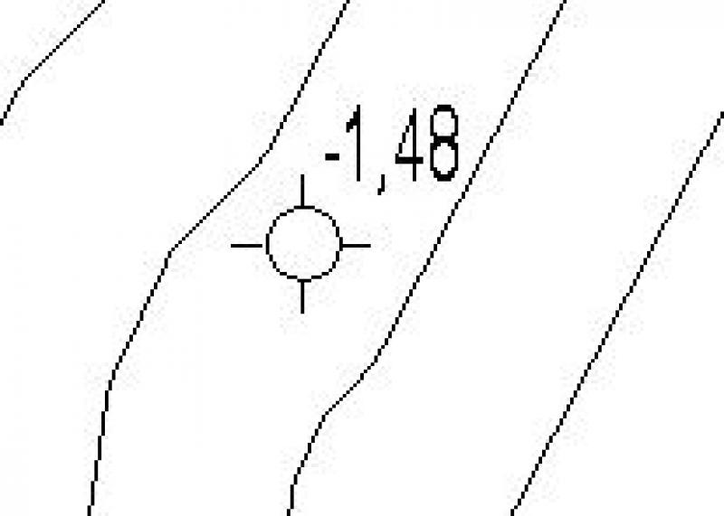
To add elevation marks to an open area, select the elevation dimensioning tool and set the reference point to the open area:
In this way, elevation values are always relative to the modeled terrain. The elevation values adaptively change their values in response to changes in terrain elevation.
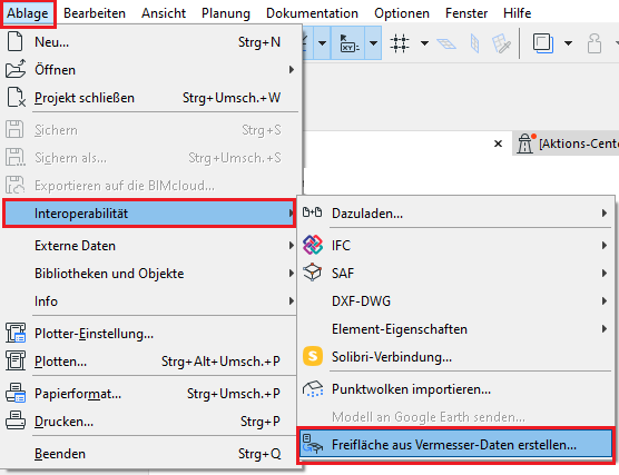
You have the option to automatically generate terrain geometry using ArchiCAD. The software can create open space directly from survey files (.txt or .xyz) without any manual work. You can find the import dialog box under File > Interoperability > Create Open Space from Survey File…
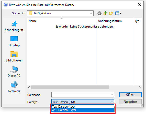
Select the appropriate file type and open the file.
No further action is required regarding the site at this stage.
No further action is required regarding the site at this stage.

Unfortunately, this content is available only to our Pro users.
If you'd like to read the full article, try the Pro account or become a Pro user.