In civil engineering, roads and sidewalks are defined as transportation structures whose alignment is influenced by connections to the existing road or sidewalk network, the locations or buildings to be served, and the local topography. The main component of a road is the so-called road structure, consisting essentially of the subgrade and pavement (foundation and surface layers), including paved shoulders and verges. The width and depth of this structure are directly dependent on the volume of traffic on the road, the weight load derived from the intended maximum vehicle size, as well as the curvature radii adapted to vehicle speed (or: turning radii, turning circles).
This article primarily focuses on the digital creation of roadways without ancillary structures, with an emphasis on the graphical representation of the road in plan views and 3D renderings, as well as the calculation of construction volumes.
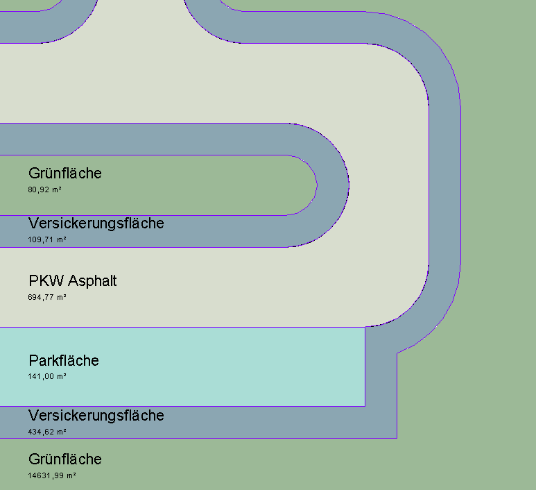
At this stage, roads and sidewalks are not yet modeled using 3D objects, but rather represented as 2D areas on site plans or floor plans, in order to identify and measure traffic areas using the simplest possible methods.
Presentation
Plan view: Floor plan only, as 3D modeling is not yet being used at this stage.
Features
In this phase, these objects are displayed only in 2D, and the required features are created by drawing surfaces. The following features must be defined in this phase:
- General: Name of the area (e.g., passenger cars)
- Generator: Delineation of the area
Labeling
In this phase, the 2D surfaces are labeled.

Face text families can be selected from Autodesk Content and loaded into the project.
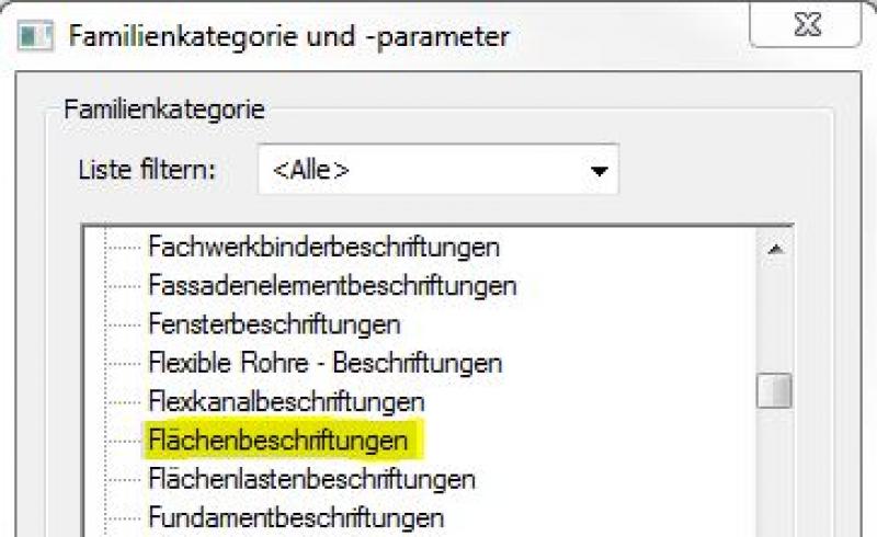
If the desired label does not yet exist, you can create a new label family using the M_General Label template. Be sure to change the category to "Area Labels":
The basic process of modeling a room surface in ARCHICAD remains the same across the various design phases and whether the space is indoors or outdoors. A detailed description of the Room Surface tool can be found in the article "Room."
Instructions
During this phase, roads and sidewalks are created by drawing 2D shapes.
For more information on creating area plans, see the article "Areas and Zones."
- Command for creating a floor plan:
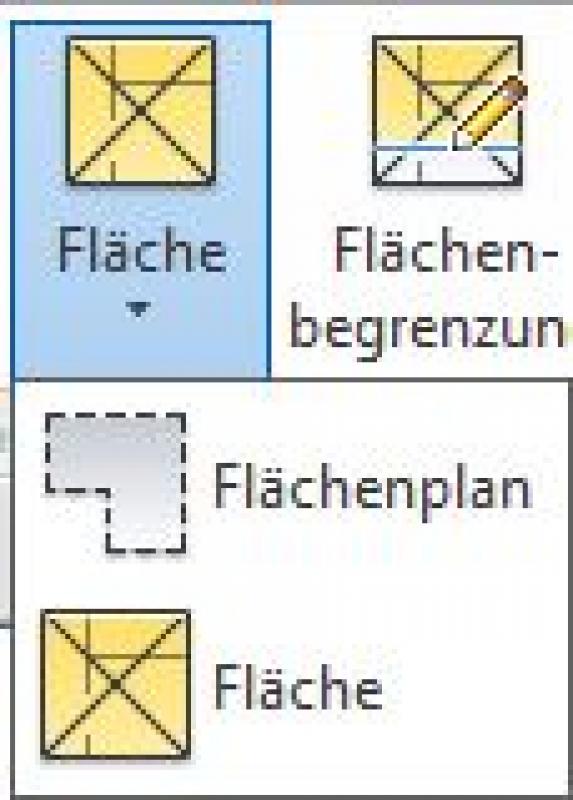
- Command for creating area boundaries:

- Command for creating surfaces:
Overview
For general information on how to use the Floor Area tool and the object libraries, please refer to Graphisoft’s basic documentation in the Help Center.
This documentation is based on the official template file 01 ARCHICAD 25 Template.tpl from the ARCHICAD 25 AUT version.
A street, as a spatial area, is treated as a building element because it is inserted into the model in three dimensions and classified as a documentation element. A building element placed as an object serves as an example for the furnishings area or determines a usage assignment for connection points/traffic routes—since it is neither structurally relevant nor space-defining, it is defined as a Building Element Class II.
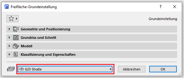
The area allocated for streets and sidewalks is on Level 620 Street:
The Room Area tool is used as described in the "Rooms" section. The room category designated for parking spaces is 09 VF (Traffic Access and Safety).
No further steps will be taken at this stage regarding the planning of roads and sidewalks.
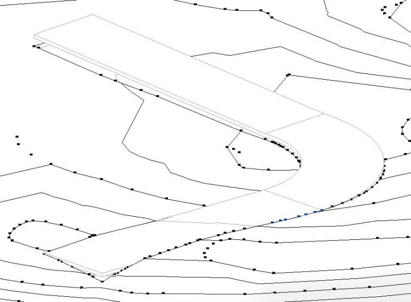
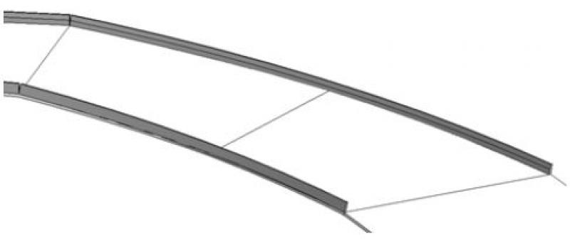
In this phase, the 2D surfaces created earlier are modeled in 3D for the first time using objects specifically designed for roads and sidewalks, and elevation and gradient data are added. The particular challenge here is to align the road alignment with the terrain while taking into account maximum and minimum surface gradients, all while minimizing the amount of terrain modification required.
Presentation
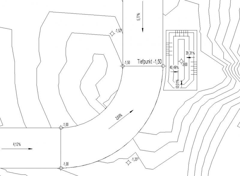
Figure 1
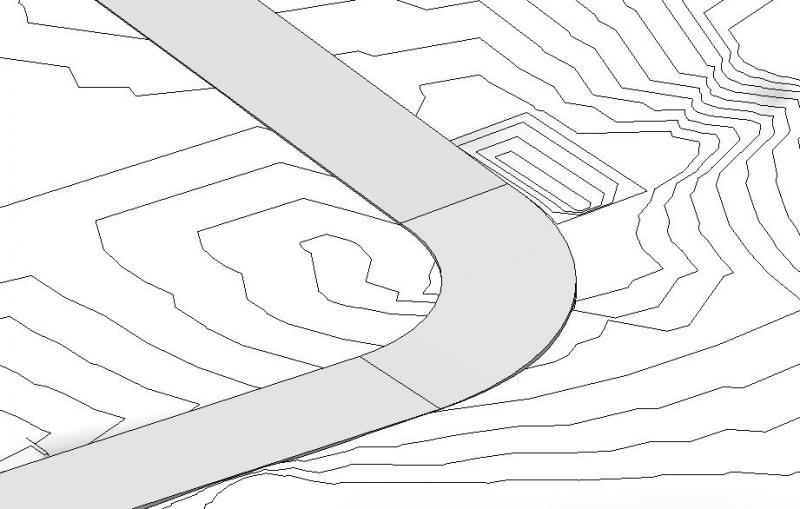
Figure 2
Features
The following characteristics are also defined in this phase:
- Generated data: geometry, elevations of road axes and edge points, gradients
Labeling
During this phase, the highest points of roads and sidewalks are marked with elevation marks and gradient values (slopes).
Instructions
During this phase, roads and sidewalks will be constructed, and their surfaces will be adjusted to the planned elevation and the terrain.
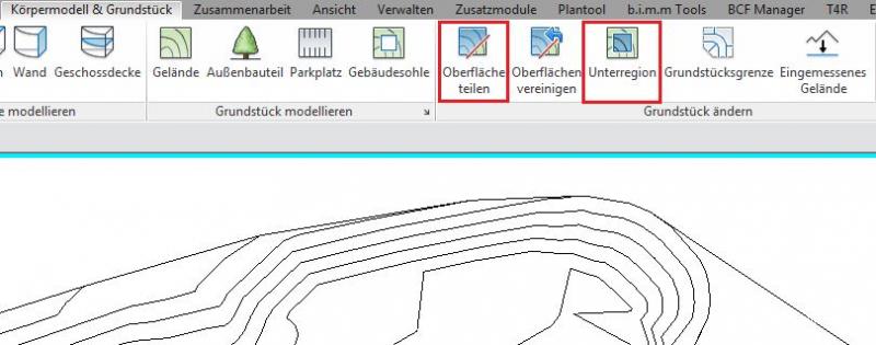
Roads and sidewalks can be modeled in Revit using terrain features.
The commands >Terrain >Split Surface and >Subregion are used for this purpose. These two commands allow the road to be displayed on the terrain, but the following points must be taken into account:
- The >Subregion command simply defines an area to which you can assign other properties (e.g., material). This area follows the terrain surface, which would make further elevation editing very difficult.
- With >Split Surface, the terrain is divided into separate parts, allowing elevation editing of the road edge points independently of the rest of the terrain. This command is therefore preferable for further elevation editing of roads and sidewalks.
Example of the >Subregion command: The road is "laid" on the surface of the terrain:
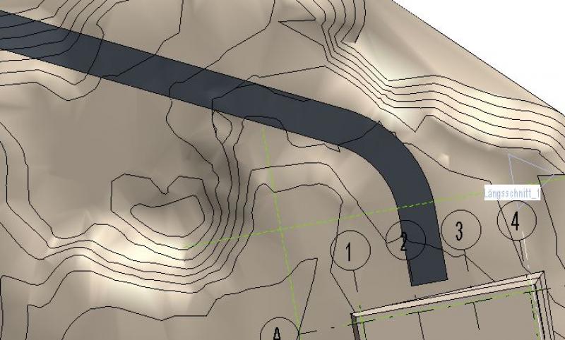
Example of the >Split Surface command: The road endpoints can be modified independently of the terrain:
For more detailed instructions on road construction, see the article "Drainage for Outdoor Areas."
Roads and sidewalks are modeled and dimensioned in the same way as terrain/topography or when using the Morph tool—elevation data is incorporated according to the surveyor's plan.
Roads and sidewalks are modeled on the 620 Road layer:
2D road model display:
3D street model visualization:
No further action is required regarding roads and sidewalks at this stage.
During this phase, the modeling of roads and sidewalks will be further refined.
Presentation
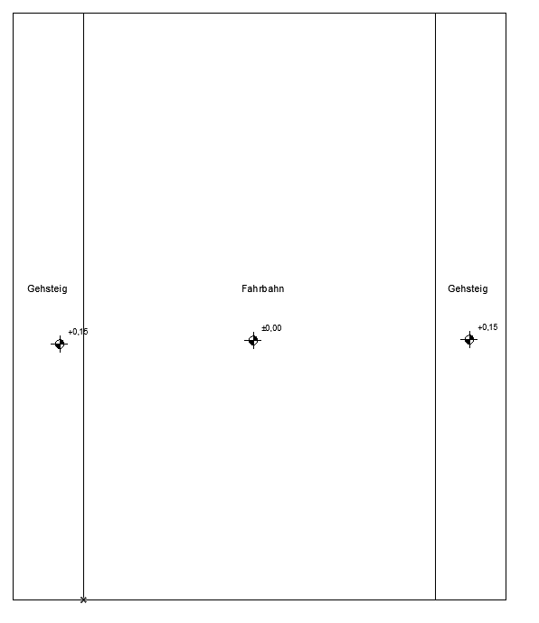
Cross-sectional view
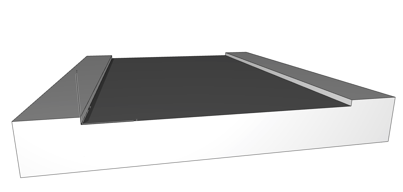
Model representation
Features
In this phase, the following additional features are added:
- Factors: Elevation, Slope
- Calculates: Cross-slope
Labeling
In this phase, the following additional labels will be added:
- Elevations with elevation marks
- Slopes with slope elevations
- Cross-slopes with 2D families
Instructions
In this phase, curbs are modeled as an additional element of roads and sidewalks.
Curbs are modeled in Revit using the command >Architecture >Part >Create Project Family (assign category, enter name) >Sweep Merge. The advantage of this method is that it allows curbs to follow sloped surfaces.
The terrain model is created and dimensioned as described in the article "Terrain: Topography."

Unfortunately, this content is available only to our Pro users.
If you'd like to read the full article, try the Pro account or become a Pro user.