Floor-cladding stairs are required because, in Revit, the stair treads and their layers should be separated from the load-bearing structural element. These are therefore two separate components that are superimposed on top of each other in terms of construction. This is comparable to floor slabs, where the floor structure is separated from the structural slab.
This article serves as a supplement to the article "Stairs: General Information." It is important to review both articles before beginning the modeling process.
Information on how to handle stairs in the early planning stages is described in the article "Stairs: General Information."
Presentation
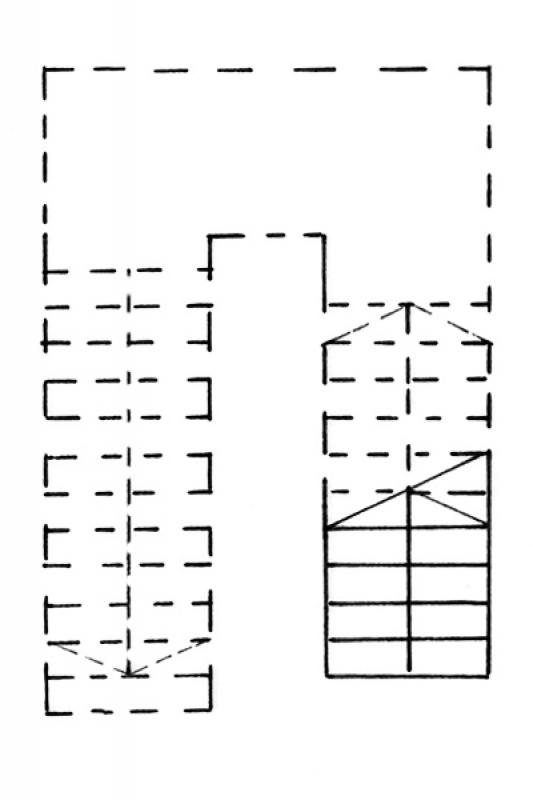
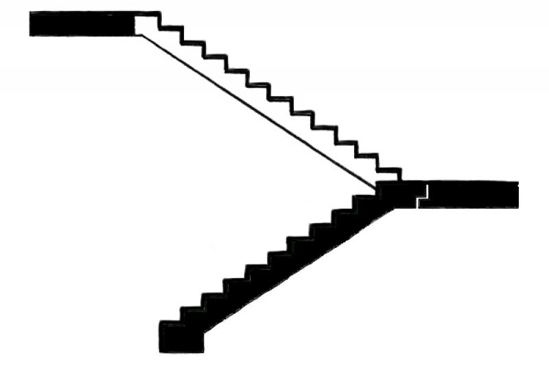
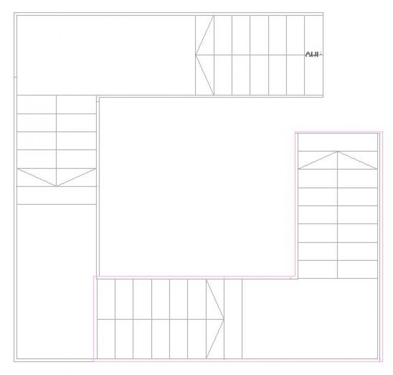
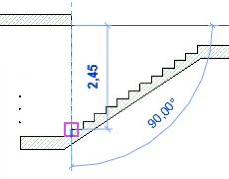
Cross-sectional view
Model representation
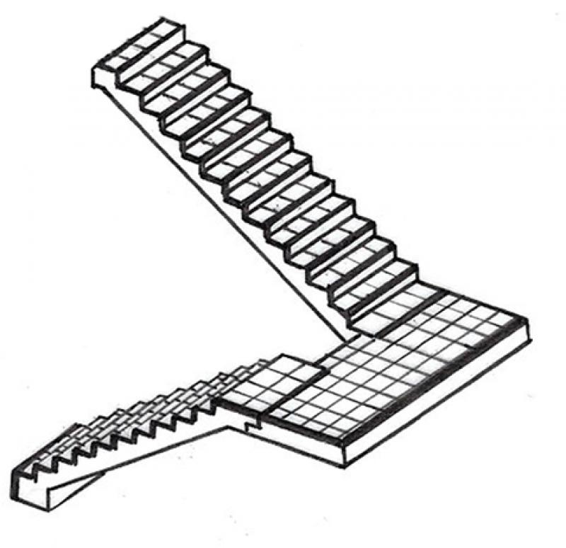
Figure 3
Features
Parameters
- Performance
Outline Information
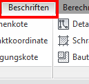
Labeling
The following features of the staircase must be labeled during the design phase:
- Gradient of individual runs
- Gradient of multiple runs
- Number of pitches and the pitch ratio
- Clear passage width (using a measuring chain)
- Run line
The labeling and dimensioning of stairs in floor plans must always be done on a per-element basis (adaptive) or within the Stair element (settings dialog). Instructions can be found in the tutorials: on labeling and on dimensioning, or under ARCHICAD Specifics > Building Elements > Stairs.
Instructions
Unfortunately, the staircase feature does not allow for the creation of exact support points for solid staircases. For this reason, the original shell design staircase is divided into a solid staircase (either a cast-in-place concrete staircase or a precast concrete staircase) and a finishing or flooring staircase.
A tread-only staircase (also known as a finish staircase) is a staircase consisting solely of treads that also serve as the base for the handrail. The tread-only staircases discussed in this article are installed directly on top of a sub-frame staircase. Tread-only stairs are also composite structures consisting of treads and risers.
To avoid unnecessary complications, stair treads should be constructed without any offset. If there are no suitable reference levels relative to the top edge of the floor, now would be a good time to establish them in advance. This simplifies the traceability of the individual work steps, especially when making corrections.
Note: Wooden stairs are not covered in this article.
Stair treads can be made of various materials; the most common are:
- Tiles
- Porcelain tile
- Concrete blocks
- Natural stone
- Wood
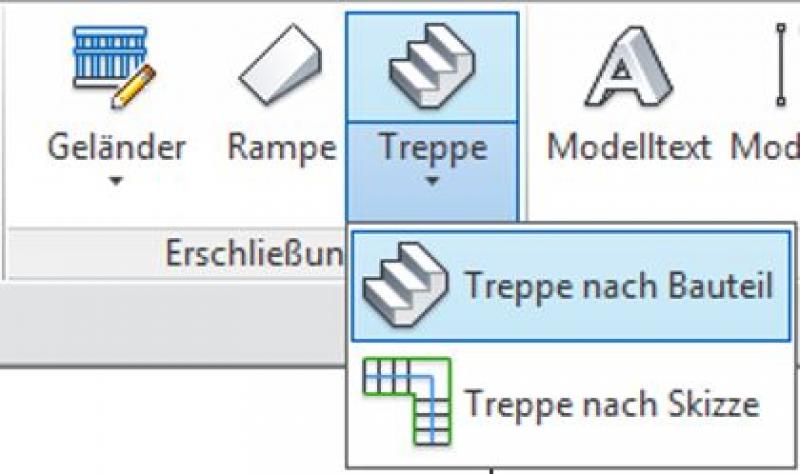
Create:
On the Architecture tab, use the drop-down menu to select Staircase -> Create Staircase from Component.
Once you have set the correct constraints or levels for the start and end of the staircase in the Properties window, you can begin sketching the staircase.
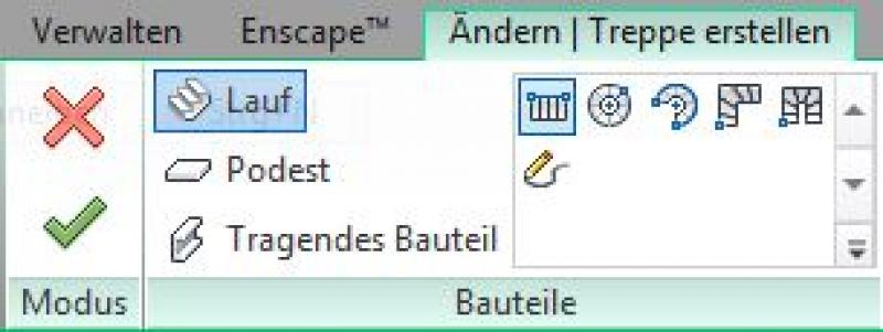
Select the staircase type (configuration: spiral with full steps, straight, etc.) and the component from which you want to start modeling (run, landing, or load-bearing component):
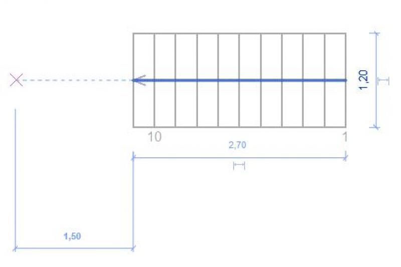
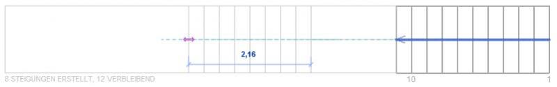
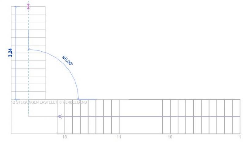
Next, sketch the staircase with the desired layout on the selected floor plan. Make sure to adhere to the minimum landing widths and the maximum number of steps in each flight up to the next intermediate landing (always follow applicable standards):
Clicking "Confirm" will exit edit mode.
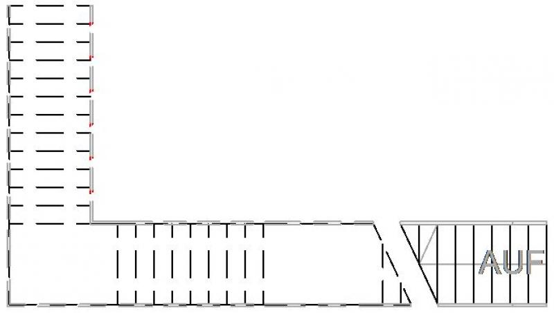
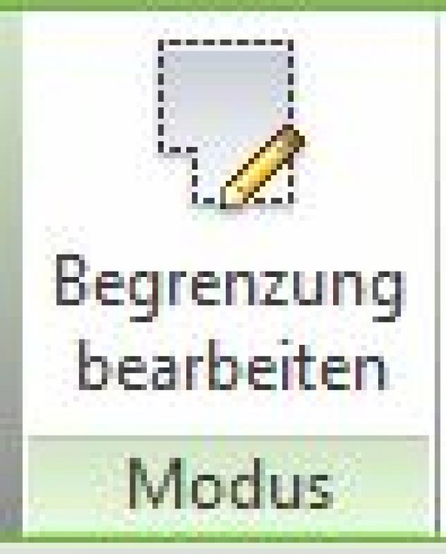
Now go to the floor plan above (stair landing) to sketch a ceiling opening. To do this, select the floor slab to be cut through and, if necessary, the floor (if it already exists) in a subsequent step, then switch to sketch mode using the "Edit with Boundary" tool.
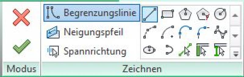
Use the drawing tools provided to draw the outline of the opening. The staircase below will be displayed as semi-transparent while you do this.
After creating a closed loop, exit sketch mode as usual by clicking the green checkmark. The ceiling cutout has now been created.

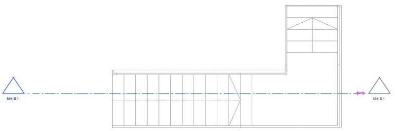
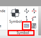
The next step is to create a test cut to verify that the required clearance height is met. To do this, select the cut icon.
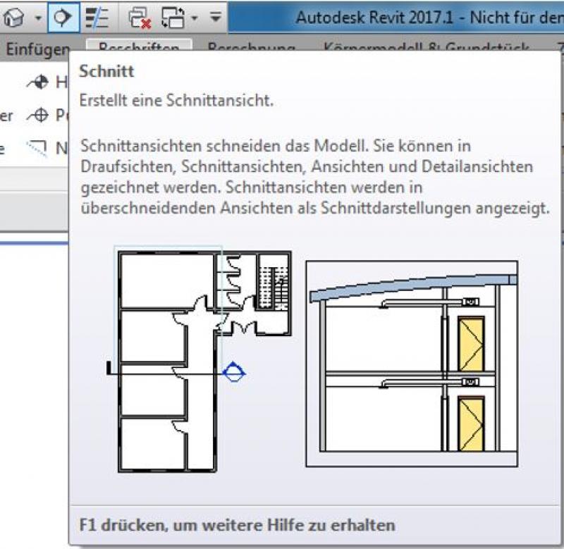
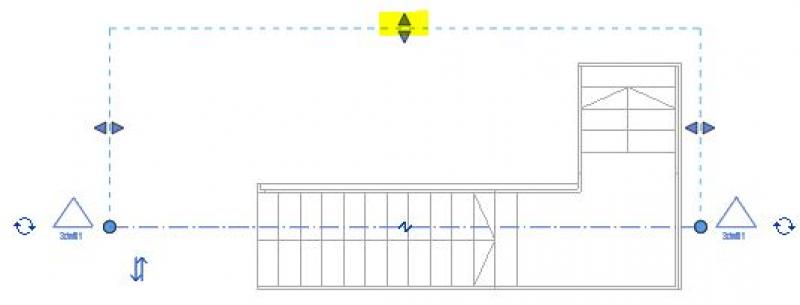
Place the piece of fabric, cut to the appropriate length, over the staircase to be inspected.
You can use the arrows to resize the selection area to the desired size.
Double-click the section icon (arrow) to switch to the section view. There, you can use the Measure tool to check the clear height.
If the headroom complies with the standard, you may proceed using the method described above (see also in-situ concrete stairs).
If the distance between the step and the ceiling is not large enough, you should switch back to the editing mode for the ceiling or floor and adjust the boundary accordingly.
In ARCHICAD, a staircase with a tread surface is not created using the Stair tool—the tread surface cannot currently be created as a separate component in the Stair tool.
One way to create this is to model the contour of the surface using a Morph body and set the classification to “Stair.”
Presentation
Plan view
Model representation
Features
Labeling
- Number of inclines and gradient
- Gradient of a single run or
- Gradient of multiple runs
- Clear passage width using measuring chains
- Rail line
The structural details of the stairs are labeled on the structural layout plan.
Instructions
The attributes are assigned to the staircase's properties so that this information can be reused in a BIM context or, for example, read via labels.
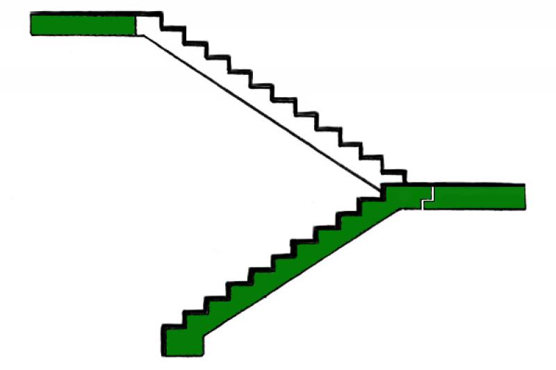
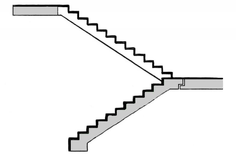
Presentation
Figure 1
Figure 2
Figure 3
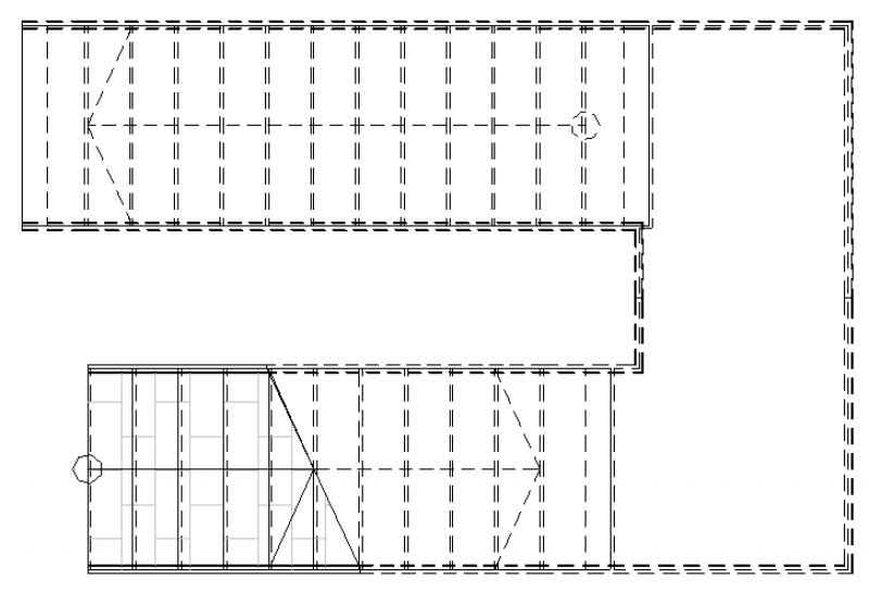
Stairwell Floor Plans (1:20)
Before:
Later:
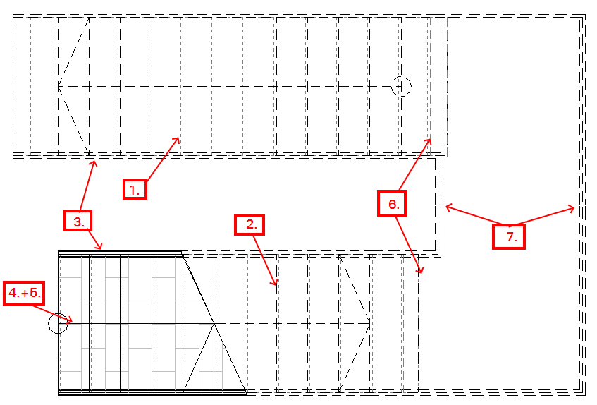
Here's how it works:
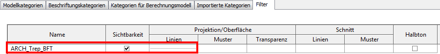
- Add the ARCH_Trep_BFT filter and override the projection lines as desired. (The narrowest line—which approximates the point line—is the Punkt_Gefälle line.)
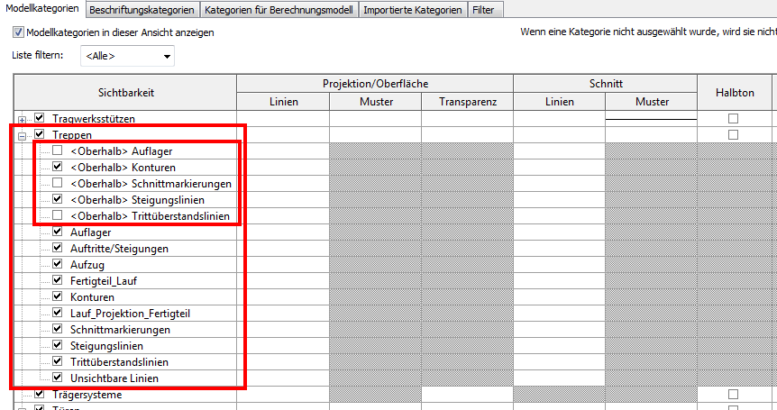
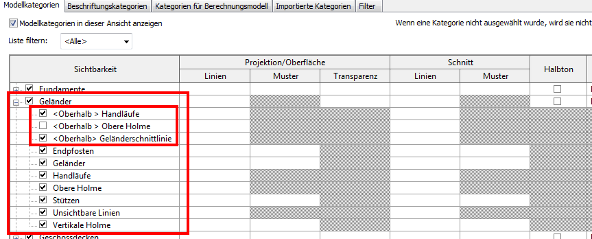
2. Using the staircase subcategories, you can, among other things, overwrite the desired lines above the cut line or hide them.
3. The railing subcategories allow you to adjust, among other things, the appearance of the railings above the cut line.
4. The leader line is created with text.
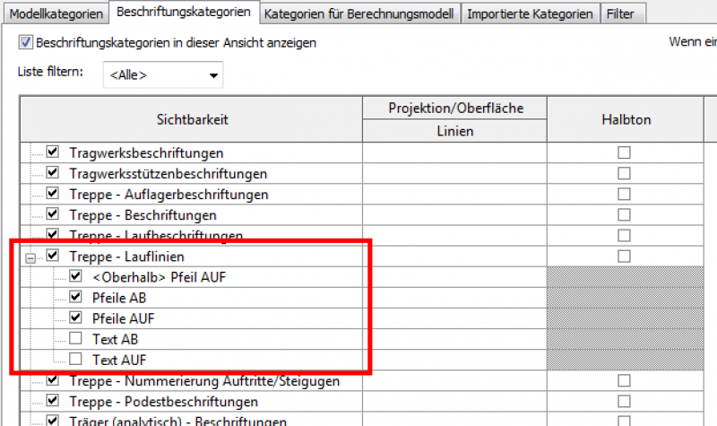
5. The appearance of the staircase’s labeling categories—the tread lines—can also be customized graphically.
6. The edges of the landing are displayed by overriding the line style. To do this, temporarily place the section plane above the landing.
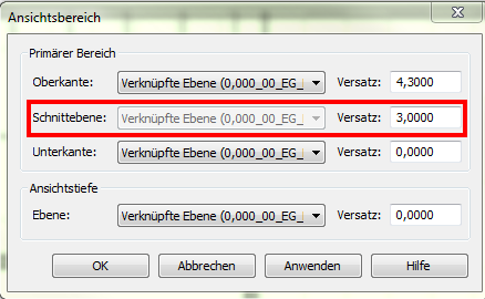
> temporarily hide the stairs
> Overwrite the lines (e.g., Hidden_Above)
> Then reset the temporary settings, including the cutting height.
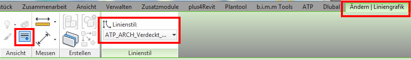
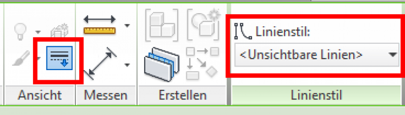
7. Remove the "unnecessary" railing separation lines at the railing junction, even if the line style is overridden (Line style: ). (You will need to click several times.)

Unfortunately, this content is available only to our Pro users.
If you'd like to read the full article, try the Pro account or become a Pro user.