Facades are a special type of interior wall. They form the vertical boundary of a building and are therefore part of the building envelope. Unlike solid exterior walls, for example, facades are constructed using lightweight construction methods.
This article describes the general approach to facades. In practice, a variety of methods are used to model such facades. On the one hand, various BIM programs offer specialized facade tools to facilitate the creation of facade systems; on the other hand, constructions made up of individual elements are also frequently used (e.g., mullions made of columns, transoms made of beams, and panels or windows as separate elements). The type of modeling depends on the geometric complexity of the desired system, the planning phase, and the discipline involved. For example, facade contractors often model in individual parts for shop and installation planning.
Search terms: glass wall, glass facade, mullion, transom, structural glazing, partition, element, infill, panel, mullion-transom, mullion transom
Presentation
Plan view
Model representation
Features
Parameters
Outline Information
Labeling
At this stage, the component is not yet labeled in the plan views.
Instructions
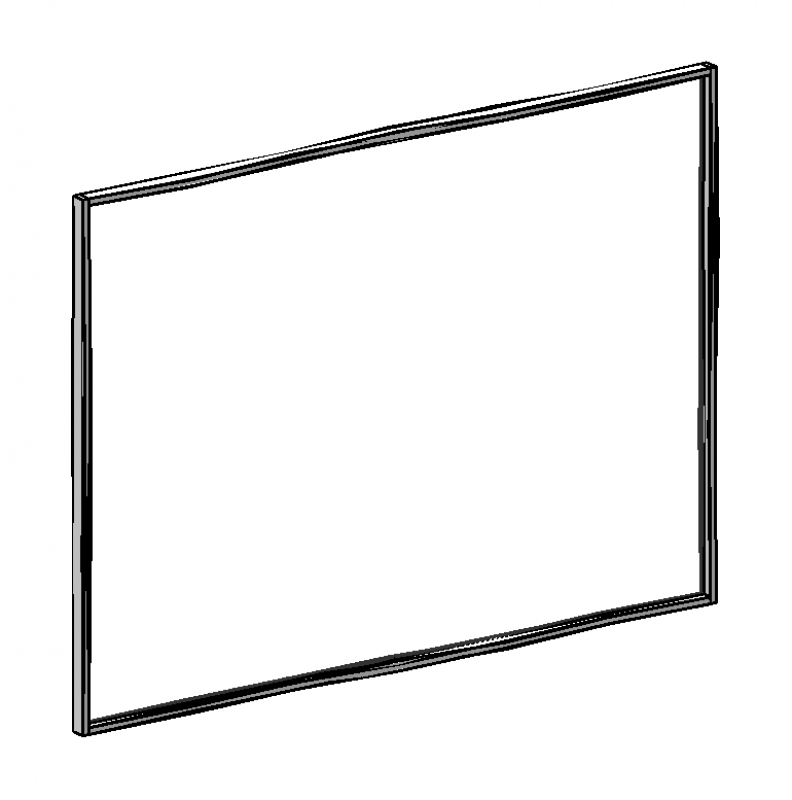
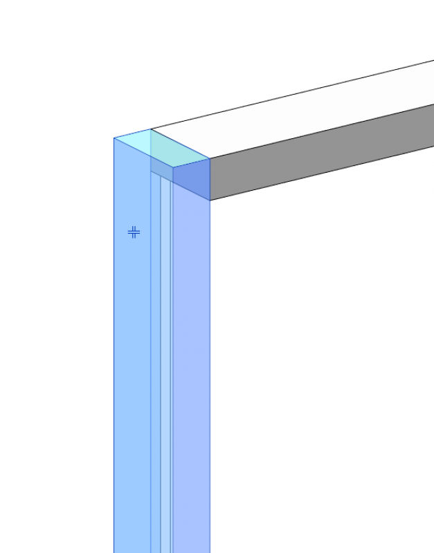
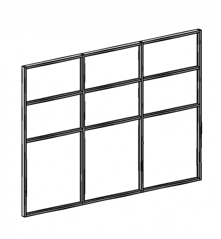
Facades are modular systems composed of grids, facade elements (panels, windows, doors), mullions and transoms, and profiles.
Element facades are generally modeled as multi-story structures, provided that this corresponds to the actual building conditions.
Generally, facades are constructed using mullions and transoms with glass or metal inserts or thin stone slabs.
During this phase, the facade posts are not processed separately from the panels.
Facades are system walls constructed from grids, facade elements (panels, windows, doors), mullions/transoms, and profiles. Element facades are generally modeled as multi-story structures, provided that this corresponds to the actual building conditions. Generally, facades are constructed from mullions and transoms with inserted glass or metal elements or thin stone slabs.
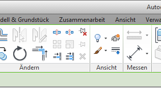
Creation
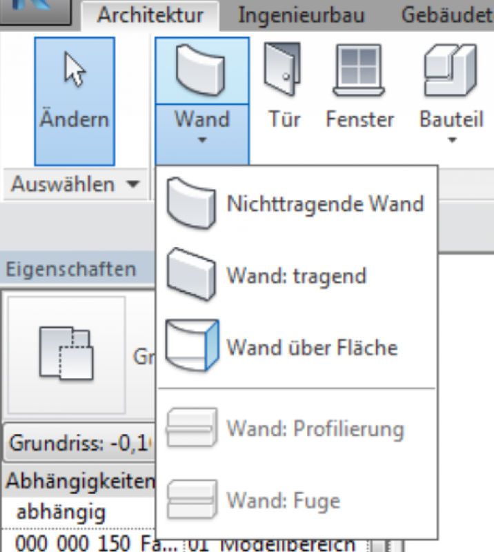
In the Architecture tab, the facade is created as a non-structural element using the Wall button.
Note: Offsets at the top and bottom should generally be avoided on facades.
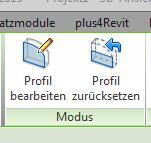
Free-form, sloped facade top edges are adjusted using the profile editing tool in the facade view or section. This allows the edited facade to be reset. However, after changing the facade length, the profile must be adjusted manually.
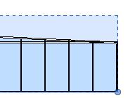
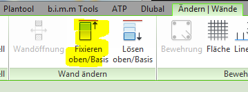
Facade edges that support a sloped floor slab must be secured to the sloped structural element above them. This securing ensures that, in the event of a change in the facade length, the upper edge is automatically adjusted accordingly.
When modifying a facade in which only certain sections are being altered as part of a different phase—such as a renovation or remodeling project—a completely new facade must be constructed in those specific sections.
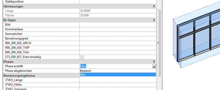
Phase settings
Phase settings for a facade are configured in the Facade system family under the Phases parameter group.
Adjusting the posts and rails
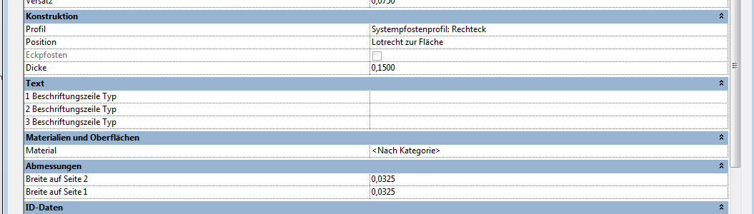
The adjustment of the dimensions of posts and rails is controlled in the type properties via the "Dimensions > Width on Side 1" and "Width on Side 2" parameter groups.
Presentation
Plan view
Model representation
Features
Feature
Parameters
Outline Information
Labeling
At this stage, it is not yet necessary to label the component in the plan views.
Instructions
Replacement of posts or rails
Procedure:
1. First, select the desired post.
2. The post is then unlocked.
3. The new post type is then selected via the Properties window.
If the desired type is not available, create a new post/beam using the type editor.
Presentation
Plan view
Model representation
Features
Parameters
Outline Information
Labeling
At this stage, it is not yet necessary to label the component.
Instructions
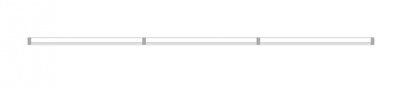
Facade divisions
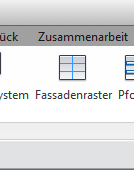
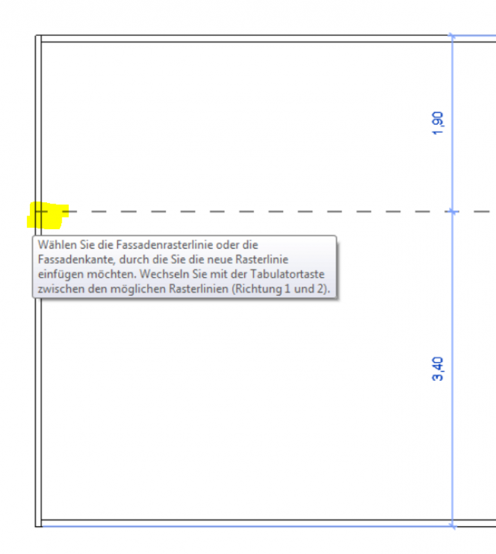
Facade divisions can be defined using the type properties or a facade grid. For facade divisions that cannot be created using the type, they are created using the Facade Grid command. However, in this case, the mullions can only be placed on the grid after the fact.
It is important to note that, with this method, the grid is only divided when you move the mouse along the outer edge of the facade.
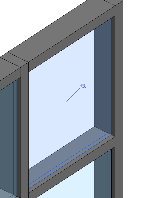
Replacement of components
The replacement of a facade panel with facade doors, facade windows, or facade openings is carried out as follows:
First, select the desired facade elements and unlock the pin.
Presentation
Plan view
Model representation
Features
Parameters
Outline Information
Labeling
During this phase, the information requested by the agency is labeled.
The components must be labeled on the floor plan using their part numbers as listed in the parts catalog, e.g., "AW-01" or "FA-01".
All wall assembly types must be checked and labeled manually. This is done using the parameters in the component and a labeling family.
For example, it may be required to label the type of glass.
Presentation
Plan view
Model representation
Plan view
Model representation
Plan view
Model representation
Features
Feature
Parameters
Outline Information
Labeling
Instructions
During this phase, only alphanumeric information regarding cost allocation is entered.
When modeling, it is best to proceed as follows:
All grids must be neatly divided without the posts. In a subsequent step, all grid axes should be carefully dimensioned, and the posts should be placed only at the end. It is advisable to create a clear type label.

Unfortunately, this content is available only to our Pro users.
If you'd like to read the full article, try the Pro account or become a Pro user.