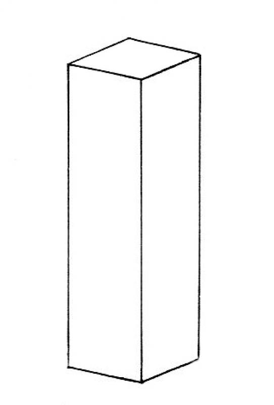
Structural columns are typically vertical, load-bearing components that primarily absorb and transfer loads along their longitudinal axis. They are part of a building’s primary structure. Depending on the construction method and building material, a wide variety of column types are used; particularly in timber construction, multiple individual columns are often grouped together in clusters.
Like all load-bearing components of a building, structural columns form an interface between architecture and structural engineering. If a model-based data transfer to structural analysis software is planned, it may be necessary to use specific modeling methods tailored to the particular software configuration. This often raises the question of what length-to-width ratio defines a component as a column versus a wall that needs to be modeled. This issue should be clarified between the architectural and structural engineering teams at the start of the project and then applied consistently throughout the entire project.
In this phase, the main supports of the structural system ("primary structure") are modeled for the first time as a minimum requirement. Materials (building materials) do not necessarily need to be defined at this stage.
Presentation
Floor plan
Model representation
Features
Feature
- Status
- Supporting element
Parameters
- Wide support
- Gross volume of support
- Rotation angle
- Total surface area of support
- Length of support
- Lateral surface area of support
- Support slope
- Net surface area
- Cross-sectional area of column
- Radius of column
- Depth of column
Outline Information
- Outer element
- Position in the grid
Labeling
In this phase, structural columns are not yet labeled in plan views.
Instructions
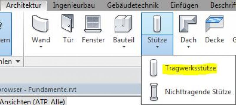
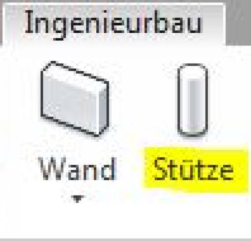
In Revit, structural columns belong to the category of the same name and are created using the command >Architecture >Column >Structural Column or >Civil Engineering >Column. Since they do not belong to the system families but rather to the so-called external (i.e., "loadable") families, they must be loaded from Revit Content as needed:
Identical commands for structural columns:
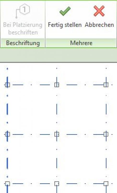
Positioning structural columns in a grid:
As a rule, structural columns can be aligned when placed by selecting a grid line or a wall. In addition, the >Grid command allows you to automatically place columns at all grid intersections in the project:
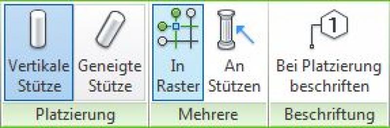
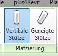
Inclined structural columns:
Structural columns can be created vertically or at an angle. The corresponding commands are located on the ribbon when placing the column:
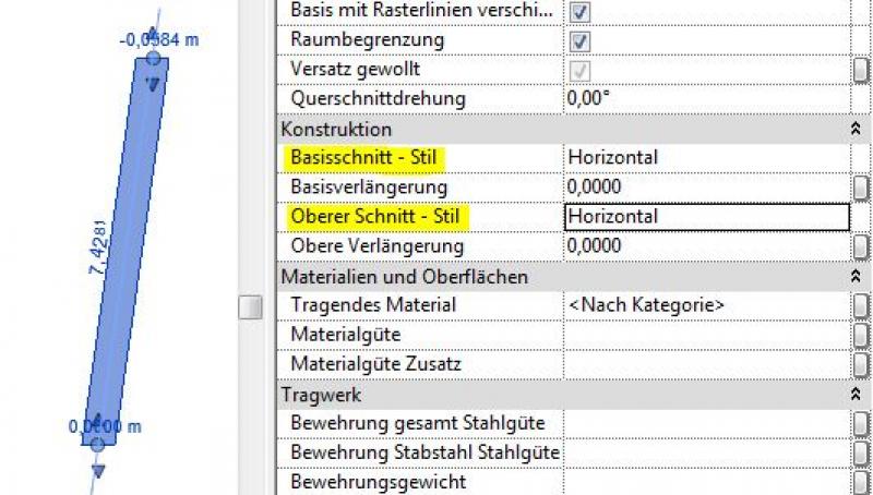
For sloped columns, the points for the top and bottom ends are specified separately in the floor plan, and the slope of the end faces is set using the "Base Section – Style" and "Top Section – Style" parameters. There are three options available for this:
- Horizontal (for horizontal column ends: see example image)
- Vertical (column ends perpendicular to the column axis)
- Vertical (for vertical column ends)
Angled support ends:
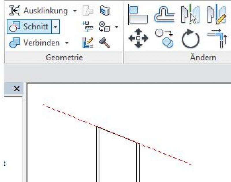
The following steps can be used to cut the ends of posts at an angle:
- Create a reference plane that represents the section plane (this is typically done in a section; see the image below)
- Use the command >Modify >Section >Cut Geometry to "cut off" the column at the reference plane (first select the column, then the reference plane)
Important additional note regarding beveled column ends:
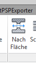
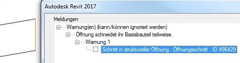
A structural column should not be trimmed using the >Architecture >Opening >By Area command, because this triggers a warning that, although it can be ignored, is saved along with the project file. As the project progresses, this can lead, on the one hand, to a significant deterioration in model performance if the number of warnings is high, and, on the other hand, to the inability to perform an IFC export required by external designers or clients.
Therefore, this approach should be avoided:
Additional column cross-sections:
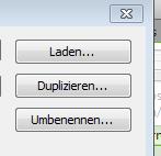
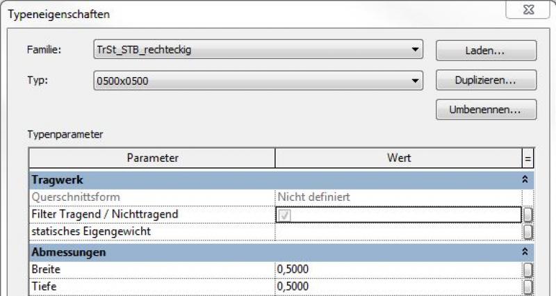
If you need an additional column cross-section that is not yet included in the family, you should create a new type using the >Edit Type and >Duplicate commands:
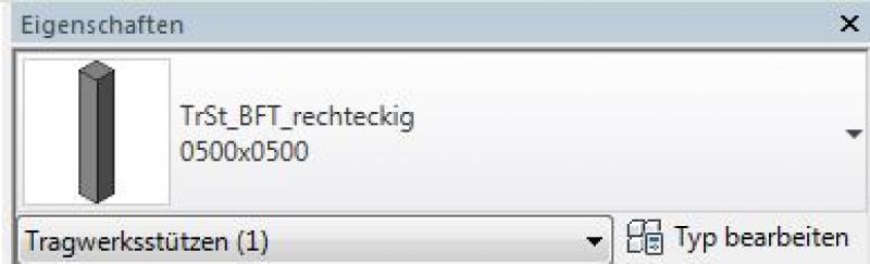
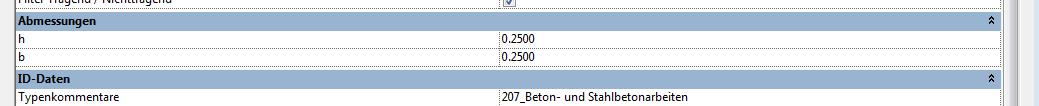
If the dimensions of the columns are changed, the relevant cross-sectional parameters h and b must be adjusted:
New families of supports:
New column families can be created using the family template >M_Structural_Column.
The following specific modeling considerations must also be taken into account for structural columns:
- Structural columns are generally modeled as load-bearing (the structural functions are automatically activated when the command is executed)
- Structural columns are also permitted to span multiple stories at this stage.
Overview
For general information on how to use the Column tool, please refer to the basic documentation provided by Graphisoft in the Help Center.
This documentation is based on the official template file 01 ARCHICAD 25 Template.tpl from the ARCHICAD 25 AUT version.
Structural elements that are defined as supports and are structurally necessary but do not form part of the room are defined as secondary structural elements.
Note: Avoid using special settings (custom graphics, room area effects) within the default column settings in order to provide other/subsequent project team members with a clear structure that minimizes the risk of errors.
The Column tool is a powerful modeling tool. You can create detailed model geometry using the column’s segmented structure. Vary the different profiles within a column element to save valuable time.
Geometry and Positioning
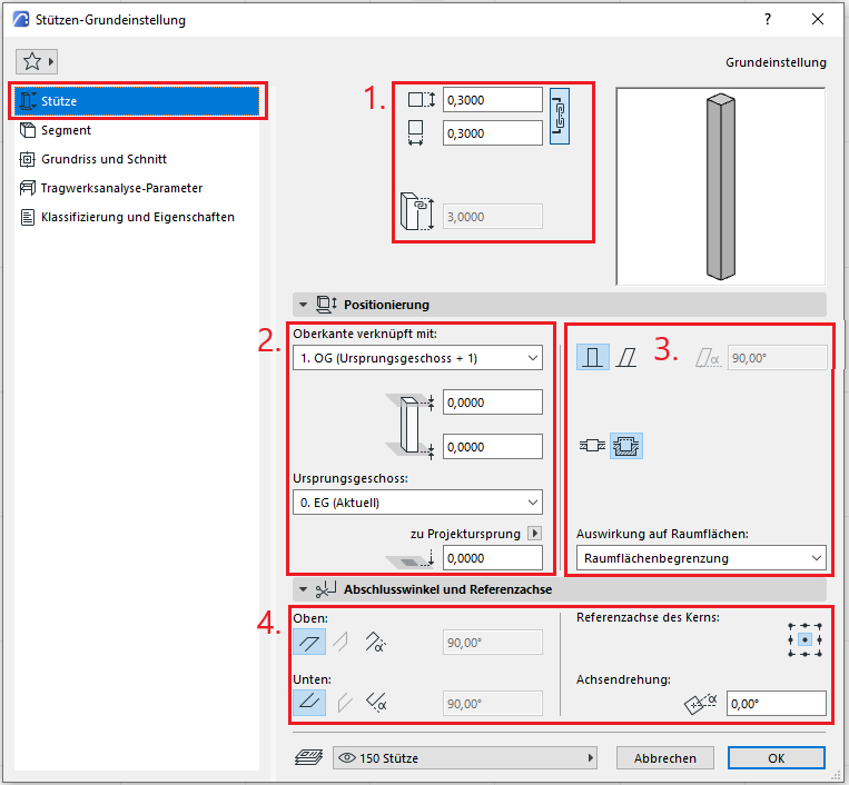
The first default setting applies to the dimensions of the column if it consists of a single segment. The input fields are disabled if the column is made up of multiple segments with different dimensions.
The second default setting defines the structural configuration and dimensions of a column:
- Rectangular – Dimensions and material to be selected
- Round – Dimensions and material to be selected
- Complex profile
In addition, the third default setting allows you to specify a cladding for the column and whether the column is inclined. For columns, the room surface boundary must always be enabled. If a different effect on room areas is selected, this must be noted (e.g., a textual note in the ID)—this alerts the next project worker that there is a deviation from the normal room area calculation—thus avoiding errors in the area evaluation.
The fourth basic setting is the selection of the anchor point for the core.
Menu item: Segment
In this menu option, you can specify the most important geometry settings at the segment level. Here, you can choose whether the support should be simple or segmented.
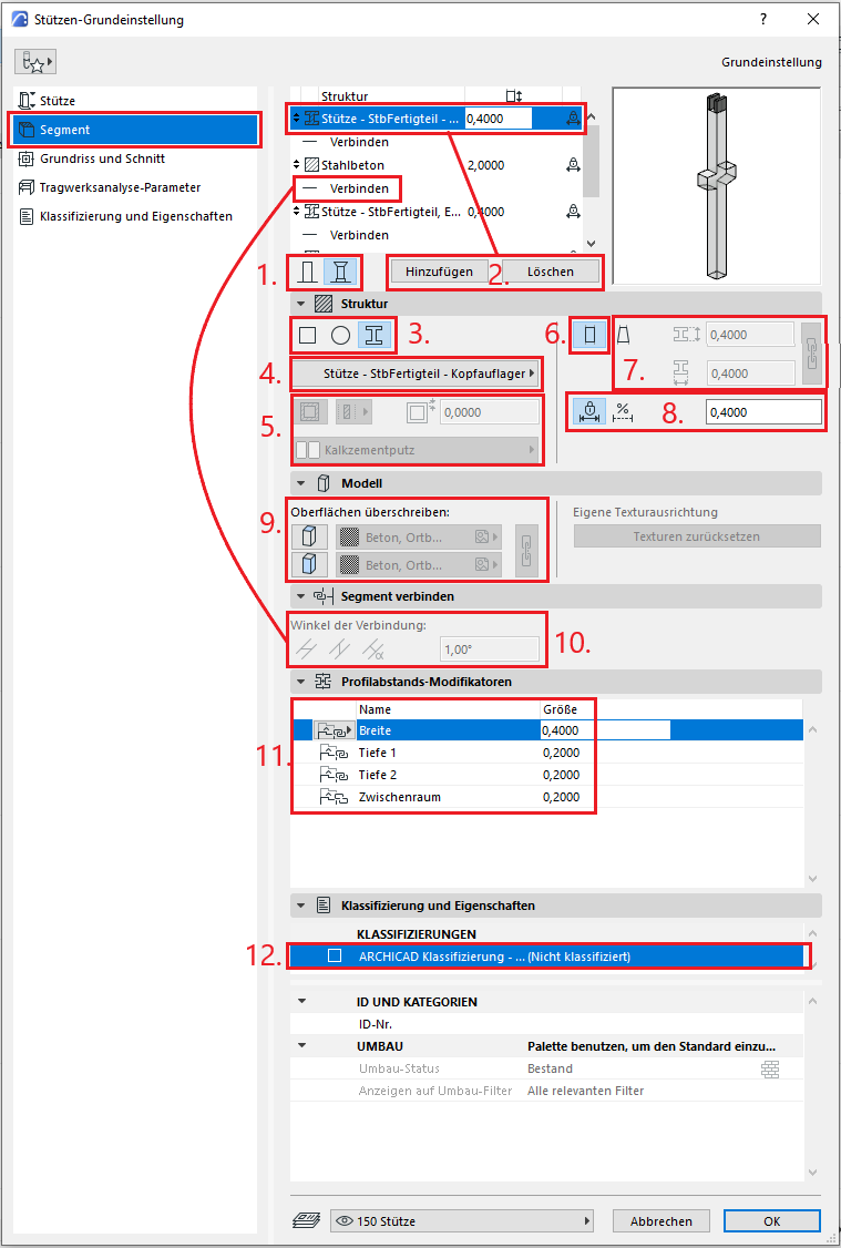
- Select the left icon if you want to use a simple support. The right icon will allow you to create a segmented support.
- You can create additional segments using the "Add" button. Click "Delete" if you no longer need them.
- Specify the cross-section of the selected segment. The three options are “Rectangle,” “Circle,” and “Profile.”
- In this pop-up menu, you can select the material for the segment. If you selected “Profile” in step 3, you can choose a profile instead of the material.
- If the cross-section in step 3 is set to “Rectangles” or “Circle,” these control buttons are activated. You can define a cladding for the column and fill in additional related parameters, such as function, thickness, and material.
- A segment has two profiles at both ends. If you activate this icon, the profiles become identical.
- If you select this icon, you can enter different dimensions for the two profiles.
- These settings control the length of the segment. You can either enter a fixed value or select the flexible length option so that the segment follows changes in the column’s total length.
- In the Model section, surfaces can be overridden manually/individually, but to ensure a traceable representation, the Graphic Override Styles option should be used for special/temporary cases.
- When you select a connection element in the segment list, you can edit the angles of the connection.
- The “Profile Offset Modifiers” tab should be used when the segment’s cross-section is set to “Profile” and a profile is selected that has at least one modifier.
- In the last tab, you can classify the individual segments and define their properties. The structure of the column’s classification system is hierarchical; the column is the parent, and the segments are the children.
Floor plan and cross-section
Model data can also be displayed using projections in floor plans, elevations, and sections—the following description explains the available options.
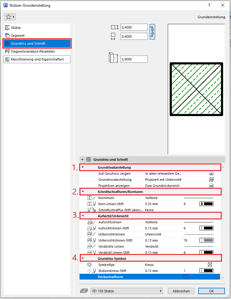
In the Floor Plan and Section section, under 1., the default setting for floor plan display is that the column is shown only on the base floor and projected with a soffit view. The projection should always be set to the floor plan area to allow for changes to the normal floor plan section plane in individual detail sets.
Section hatching and outlines under item 2 should not be overridden by individual support settings—these should always be set centrally in the profile to apply to all components, or the "Graphical Override Styles" option should be used for special or temporary display changes.
Setting 3 for the bottom view line is defined using the "Bottom View" line to ensure that all bottom views are displayed consistently.
In addition, you can select the floor plan icon under 4.
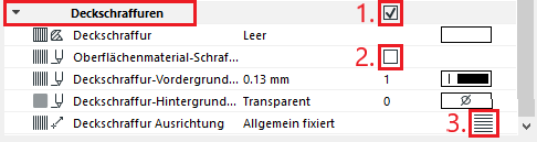
- If you want to set an overlay hatch for the column, check the box on the right to edit the hatch settings. Select one from the catalog…
- or use the surface material’s hatch pattern.
- You can also define the orientation of the surface hatch by clicking the icon on the right in the row.
Menu item: Structural analysis parameters
The under-brace tool is one of the model elements that can be represented in the structural analysis model. This requires that the column has been defined as a load-bearing element. For more information on the structural analysis model, see the article: Model Preparation for Structural Design in ArchiCAD.
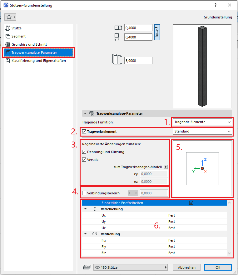
- You can specify the load-bearing function of the column
- As an additional option, you can use the checkbox to specify whether the column should function as a structural element or not. In the dropdown menu, you can select the type of structural analysis unit.
- The structural analysis unit differs from the physical model element. You can manually adjust the unit or apply the automatic, rule-based changes.
- You can also specify the connection area manually if the checkbox is selected.
- You can manually change the position of the structural analysis unit in the preview window if the checkboxes in step 3 are unchecked.
- You can enter the end constraints in this section.
Menu item: Classification and Properties
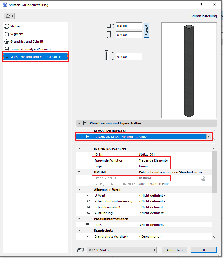
The element classification is the first definition in the Classification and Properties section—see also Classification. When a classification is selected on a column, only those properties in the lower field area that are available for this classification according to IFC properties and the Properties Manager are displayed.
The three features that also serve another purpose within ArchiCAD are
Supporting function, location, and conversion status—these factors affect either the structural representation method, the envelope function (in other programs), or the conversion filter. All other characteristics must be selected individually or determined in accordance with the project’s organizational guidelines (e.g., project manual or organizational manual).
During this phase, the structural engineering team assesses the load-bearing capacity of the structural columns and, based on that assessment, selects a material (construction material).
Presentation
Floor plan
Model representation
Features
Feature
- Fire resistance class
Parameters
Outline Information
Labeling
In this phase, structural columns are not yet labeled in plan views.
Instructions

Material assignment:
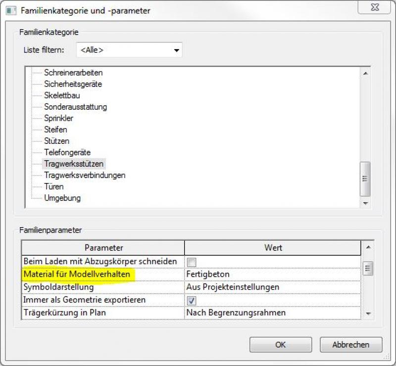
Material assignment for structural columns is performed in two steps:- Material assignment for structural analysis: This is done by selecting the family parameter >Material for model behavior in the family (here using a precast concrete column as an example):
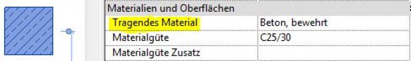
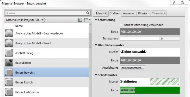
- Material assignment for graphical representation: This is done by selecting the option in the member parameters > Load-bearing material in the project (here using a reinforced concrete column as an example):
The basic process for modeling a column in ARCHICAD remains the same throughout the various design phases.
The new features and parameters added for this phase must be entered in the appropriate fields of the component's settings dialog.
The description of the settings dialog and the corresponding procedure can be found in an earlier section of this article.
The labeling and dimensioning of the component should always be done associatively. Instructions on how to do this in ARCHICAD can be found in the relevant articles.
In this phase, structural supports are supplemented with structural design information.
Presentation
Floor plan
Model representation
Features
- Earth-touching element
Labeling
In this phase, structural columns are labeled only in the structural engineering drawings:
- Load diagram: Load application
- Position diagram: Position
Labels for structural columns can be obtained from Revit Content.
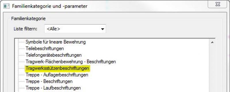
New labels can be created using the label family template >M_General Label. In the new family, the category should be changed to "Structural Column Labels" using the >Family Category and Parameters command:
Instructions
In this phase, the structural columns are grouped by floor to enable a mass analysis on a floor-by-floor basis.
Procedure for dividing a structural column:
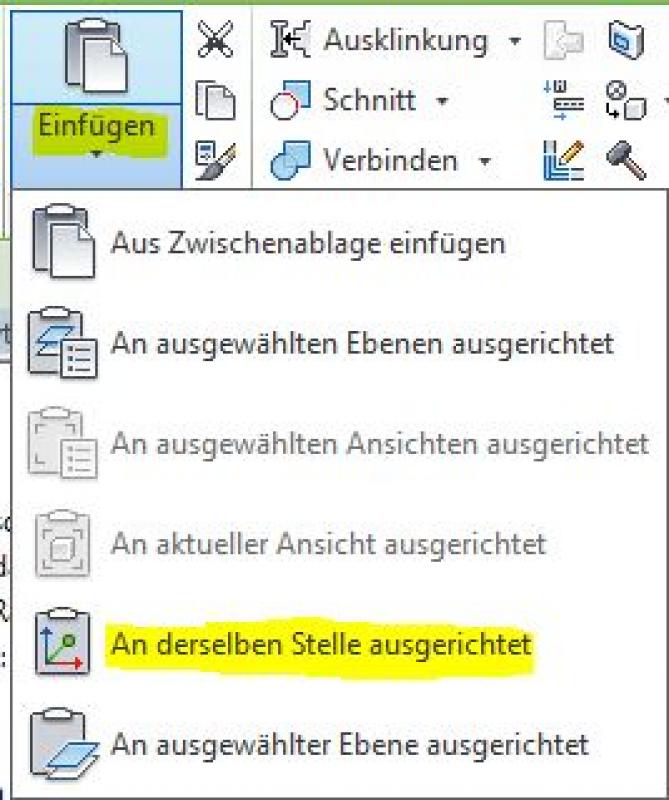
- Copy the support to the clipboard and paste it in the same location, aligning it. This places two identical components in the same position in the model.

- Align the base level (bottom edge of the column) and top level (top edge of the column) of the two structural columns with the corresponding levels in the various floor plans. This means that, while the components are still located in the same place on the floor plan, they have been split in terms of height.
The basic process for modeling a column in ARCHICAD remains the same across the various design phases.
The new features and parameters added for this phase must be entered in the appropriate fields of the component's settings dialog.
The description of the settings dialog and the corresponding procedure can be found in an earlier section of this article.
We recommend selecting the "Complex Profile" setting.
For columns, it is particularly important to set the “Load-bearing function” to “Load-bearing elements” under Categories and Properties, and to set the “Core” option for the reinforced concrete material in the Complex Profile. This setting enables the column to be displayed without its additional layers (e.g., insulation) according to the profile when using the “Only the core of the load-bearing elements” structural representation. The column evaluation also draws on this information and can display it (along with all other information assigned to the column).
The use of complex profiles allows for highly effective centralized control of the structural elements: as soon as a change must be made to the dimensions of a column, all columns that reference that complex profile are updated accordingly; this eliminates the risk of individual structural elements being “overlooked.”
At this stage, at the latest, a further distinction is made between the various design options for structural components. For example, a distinction must be made between cast-in-place and precast structural columns.
Presentation
This is where the different countries differ: In Austria, submission drawings are color-coded by building material; this classification is based on the reinforced concrete classification specified in the Vienna Building Code.
Floor plan:
Features
Labeling
During this phase, structural columns are labeled by the architectural team as "ready for approval."
These include:
- Structural columns - Cross-sections (width x depth)
The structural columns are labeled with the designations derived from the structural analysis, including their cross-sections. Ideally, the labeling is performed using a family that retrieves the necessary information from the parameters and properties of the structural components:Instance parameters:
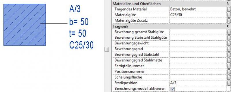
Type parameters
The new features and parameters for this phase must be added in the appropriate sections of the component's settings dialog.
The description of the settings dialog and the corresponding procedure can be found in an earlier section of this article.
The labeling and dimensioning of the component should always be done associatively. Instructions on how to do this in ARCHICAD can be found in the relevant articles.
Instructions
Country-specific color settings:
In Revit, the specific color schemes for submission drawings (permit drawings) are defined in the material (there is no type setting for the color fill at a coarse scale for structural columns): Color in the material:
The basic process for modeling a column in ARCHICAD remains the same throughout the various design phases.
The new features and parameters added for this phase must be entered in the appropriate fields in the component's settings dialog.
The description of the settings dialog and the corresponding procedure can be found in an earlier section of this article.
We recommend selecting the "Complex Profile" setting.
For columns, it is particularly important to set the “Load-bearing function” to “Load-bearing elements” under Categories and Properties, and to set the “Core” option for the reinforced concrete material in the Complex Profile. This setting enables the column to be displayed without its additional layers (e.g., insulation) according to the profile when using the “Only the core of the load-bearing elements” structural representation. The column evaluation also draws on this information and can display it (along with all other information assigned to the column).
The use of complex profiles allows for highly effective centralized control of structural elements: as soon as a change must be made to the dimensions of a column, all columns that reference that complex profile are updated accordingly; this eliminates the risk of individual structural elements being “overlooked.”
During this phase, all information required for the contract award (concrete grade, etc.) is added to the structural columns. In addition, the member is reinforced. Depending on the collaboration scenario, this can be done in 3D within the member or in 2D, independent of the model.
Presentation
Floor plan
Model representation
Features
- Number of brackets
- Gross weight of support
- Net weight of support
- Net volume of support
- Reference
Parameters
Outline Information
Labeling
During this phase, the substrate is fully labeled and marked.
Architectural Floor Plan:
- Dimensioning of all column edges and column cross-sections
- Lower and upper edges of columns (relative to the lower and upper edges of the rough slab)
Structural Design Overview:
- Dimensioning of all column edges and column cross-sections
- Lower and upper edges of columns (relative to the lower and upper edges of the rough slab)
- All information relevant to the structural shell
Instructions
The information regarding the reinforcement to be used in this phase must be provided by the structural engineering team and incorporated into the foundation design.
For information on creating new families in the Structural Annotations category, see the instructions in this article under the section >Design >Annotation >Revit Workflow
The basic process for modeling a column in ARCHICAD remains the same throughout the various design phases.
The new features and parameters for this phase should be added in the appropriate sections of the component's settings dialog.
The description of the settings dialog and the corresponding procedure can be found in an earlier section of this article.
The labeling and dimensioning of the component should always be done associatively. Instructions on how to do this in ARCHICAD can be found in the relevant articles.
We recommend selecting the "Complex Profile" setting.
For columns, it is particularly important to set the "Load-bearing function" to "Load-bearing elements" under Categories and Properties, and to set the "Core" option for the reinforced concrete material in the Complex Profile. This setting enables the column to be displayed without its additional layers (e.g., insulation) according to the profile when using the structural representation "Only the core of the load-bearing elements." The column evaluation also uses this information and can display it (along with all other information assigned to the column).
The use of complex profiles allows for highly effective centralized control of structural elements: as soon as a change needs to be made to the dimensions of a column, all columns that reference that complex profile are updated accordingly; this eliminates the risk of individual structural elements being “overlooked.”

Unfortunately, this content is available only to our Pro users.
If you'd like to read the full article, try the Pro account or become a Pro user.