In the construction industry, “landscaping” refers to the design of the site’s ground surface or building surfaces (roof and facade greening) through the creation of green spaces or the planting of ornamental plants of any kind (trees, shrubs, perennials, etc.). In a BIM model, this primarily involves the representation of green spaces and plants in the context of building exteriors or roof and facade surfaces.
Unfortunately, a reasonably realistic representation of plants—especially in 3D—requires a high level of detail; therefore, it is important to choose an appropriate level of abstraction, particularly in projects with many plants. For performance reasons, a more abstract representation is generally recommended. Different BIM programs offer various solutions for adjusting the level of detail for plants.
Search terms: plants, garden, greenery, tree, trees, shrub, shrubs, bush, hedge, meadow, lawn, grass, Dtai, Bepf, RPC, exterior component, exterior
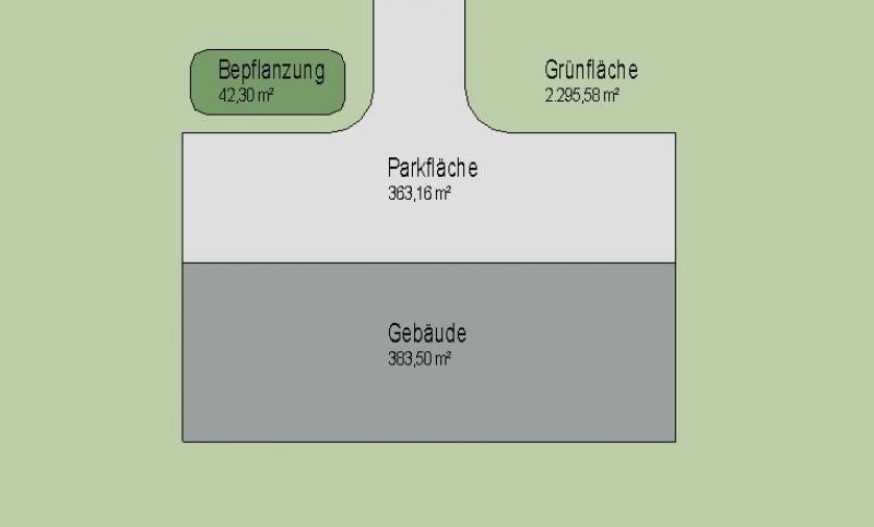
In this phase, the landscaping is not yet represented using 3D objects, but only using 2D areas and 2D elements in site plan or floor plan views, in order to identify planting areas and measure any required areas as efficiently as possible.
Presentation
Plan view (floor plan; not a 3D model, as 3D elements are not used in this phase)
Features
In this phase, these objects are displayed only in 2D, and the required features are created by drawing surfaces or offsetting 2D elements. The following features are defined in this phase:
- General: Name of the area
- Generator: Boundary of the area
Labeling
In this phase, the 2D surfaces are labeled.
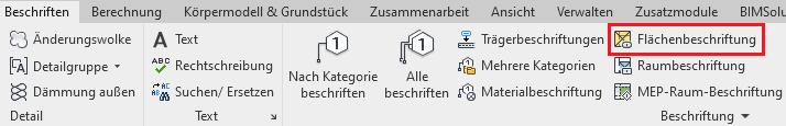
Command for labeling areas: >Label >Area Label
Face text families can be selected from Autodesk Content and loaded into the project.
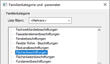
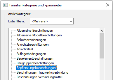
If the desired label does not yet exist, you can create a new label family using the M_General Label template. Be sure to change the category to "Area Labels":
The basic process of modeling a room surface in ARCHICAD remains the same across the various design phases and whether the space is interior or exterior. A detailed description of the Room Surface tool can be found in the article "Room."
Instructions
In this phase, landscaping is typically created by drawing 2D areas or using 2D symbols.
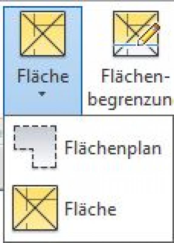
Before creating areas, you should first create a special floor plan called an "area plan," then define the area boundaries, and finally create the areas:
- Command for creating a floor plan:
>Architecture >Floor Plan >Floor Plan or >View >Top Views >Floor Plan
- Command for creating area boundaries:
>Architecture >Land Use Restrictions

- Command for creating surfaces:
>Architecture >Spaces >Spaces
Overview
The basic process of modeling a room surface in ARCHICAD remains the same across the various design phases and whether the space is interior or exterior. A detailed description of the Room Surface tool can be found in the article "Room."
For general information on how to use the Floor Area tool and the object libraries, please refer to Graphisoft’s basic documentation in the Help Center.
This documentation is based on the official template file 01 ARCHICAD 24 Template.tpl from the ARCHICAD 24 AUT version.
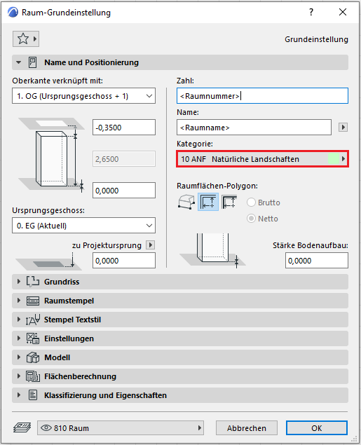
A planting area treated as a spatial element is handled similarly to a building component, as it is inserted into the model in three dimensions and classified as a documentation element. A planting area placed as an object is used in the furnishings section to illustrate or define a specific type of planting.
The space allocated for plants is 80 room stamps:
No further measures regarding planting will be taken at this stage.
In this phase, the plants are modeled in 3D for the first time.
Presentation
Plan view
Model representation
Features
The following characteristics are additionally defined in this phase by the creation of these objects:
- Producer: Height (of trees, shrubs, etc.)
Labeling
Labeling is performed using label elements for the corresponding 3D objects.
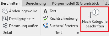
Command for labeling plantings: >Label >Label by Category
Plant label families can either be selected from Autodesk Content or created by starting with the M_General Label template and changing the category to Plant Labels:
The labeling and dimensioning of the component should always be done associatively. Instructions on how to do this in ARCHICAD can be found in the relevant articles.
Instructions
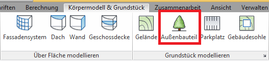
Plants are placed using the >Building Model & Site > Exterior Element command and are classified under the Revit category "Landscaping" (in rare cases, they may also be classified under the "Site" category).
Alternatively, landscaping can also be placed via >Architecture > Element.
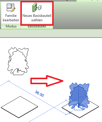
Families in the "Planting" category automatically detect the underlying base component. This could be, for example, floor slabs or terrain. This allows them to be placed in both the floor plan and the 3D view.
Important: When placing vegetation, you should use the same layer that is assigned to the base component.

If there is no reference to a base component, you can create one using the >Select New Base Component command. If the planting is assigned to a base component, it will automatically adjust when the height of the base component changes.
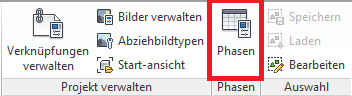
If a distinction is made between existing and new plantings, they can be categorized using Revit phases.
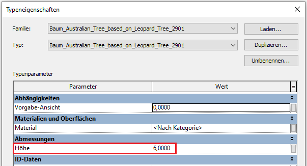
Plant heights:
If you need to change the height of plantings, a type parameter is usually available for this purpose:
RPC Families Guide
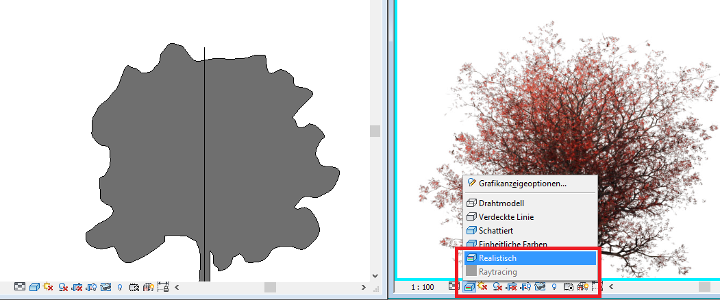
For a photorealistic representation of landscaping, the concept of so-called RPC (Rich Photorealistic Content) elements is available, which is essentially based on a photo-based representation of the object from several different angles. Objects of this type can be obtained from ArchVision, the leading manufacturer in this field. If a so-called RPC element is stored in a family, the object can be rendered photorealistically in views, sections, and 3D using the 'Realistic' image style. However, since this rendering style is very computationally intensive, it should be activated either only temporarily or in views that are to be plotted.
To place an RPC tree, use the same command as for other plants:
>Building model & lot >Exterior component
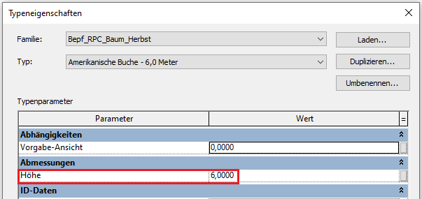
Revit Content provides pre-configured families for this purpose, categorized by tree species and size, with the symbol’s appearance determined by the family type. If the required size is not available, a new family type should be created. Within this family, the plan symbol and the photo object can be scaled separately to the correct size.
Height of RPC elements:
If you want to change the height of RPC elements, a type parameter is available for this purpose, just as with the other planting families:
Overview
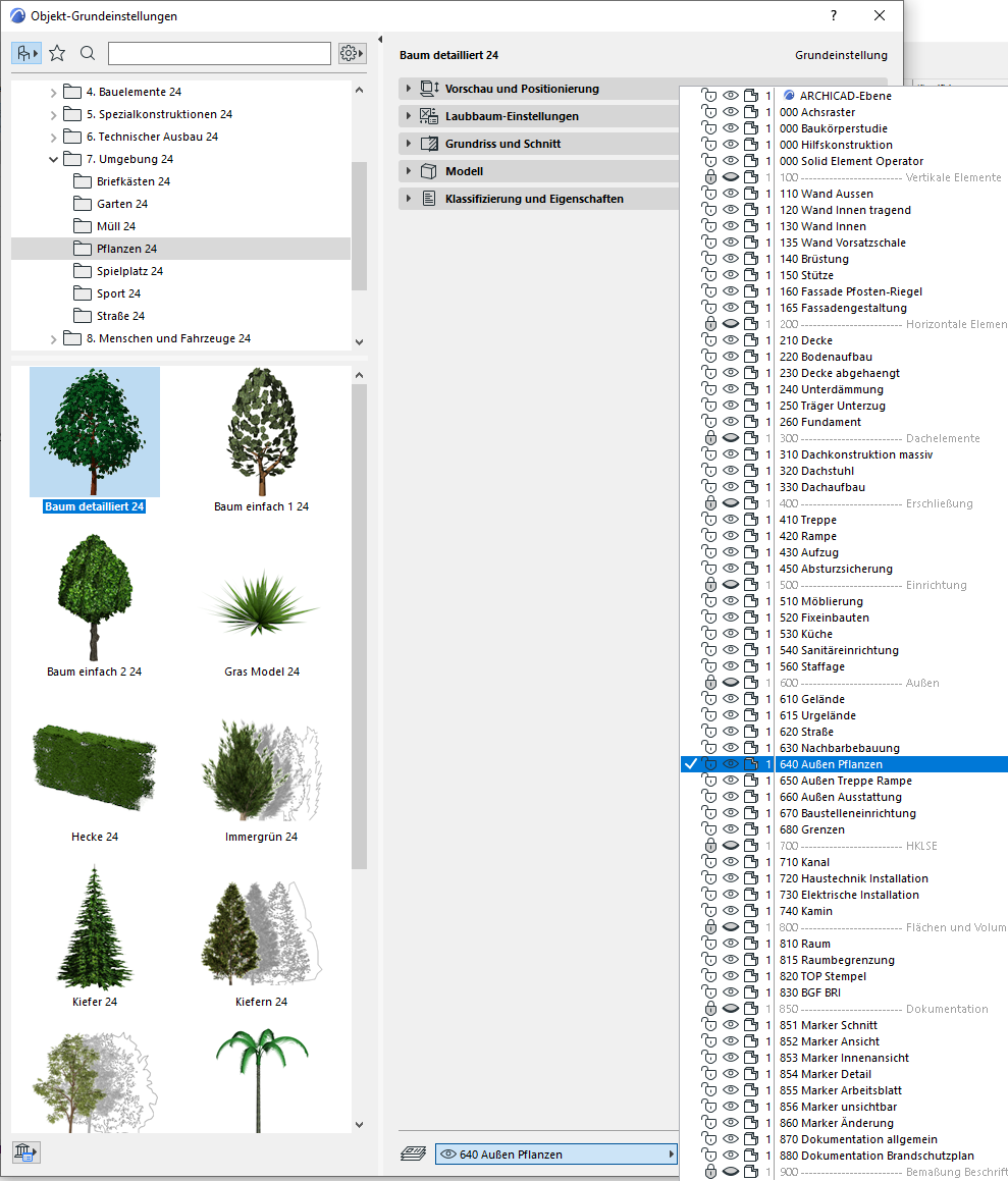
Outdoor plantings can be displayed in both 2D and 3D and are available in the library as corresponding objects.
The layer for planting objects is 640 Outdoor Plants:
Preview and Positioning
The plant object is correctly placed at floor level 0 (= OKRD) or on the terrain model.
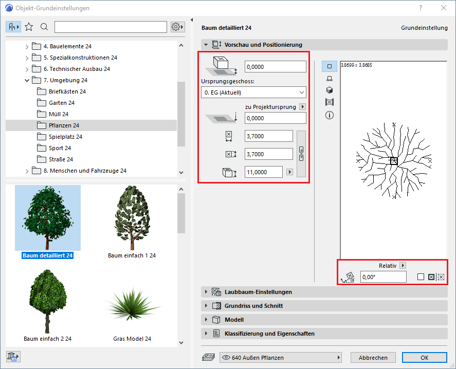
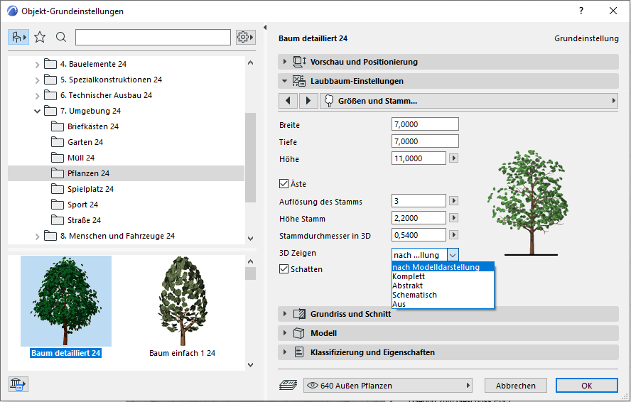
Settings
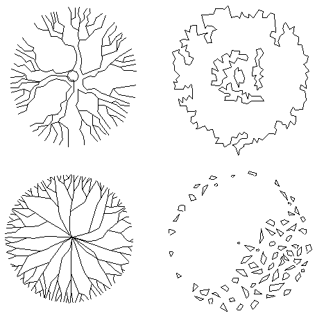
For plant objects, the 3D display can be set in the settings to Model View, Complete, Abstract, Schematic, or Off—this determines the level of detail and the display style for an object.
2D symbols:
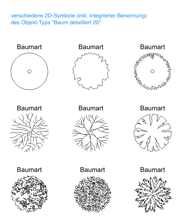
For most plant objects, integrated labeling is also available in the floor plan area.
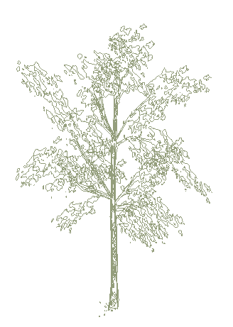
3D objects (including 2D symbols):
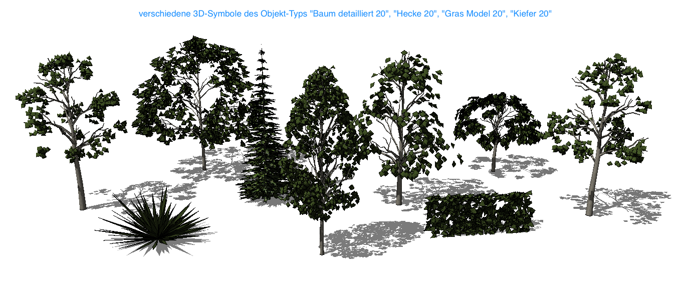
When creating a 3D rendering, pay attention to the resolution and foliage density: the more detailed a plant object is set to be, the more processing power is required.
No further action regarding the plantings is required at this stage.
No further action regarding the plantings is required at this stage.

Unfortunately, this content is available only to our Pro users.
If you'd like to read the full article, try the Pro account or become a Pro user.