In the construction industry, "excavation" refers to the removal of soil from a foundation pit required for a building's foundation; in the context of a BIM model, the primary focus is on capturing the excavation volumes and representing the edges and slopes of the cut.
In the process, the original terrain is modified accordingly, and the volumes of excavated and backfilled material required to create the new terrain profile are calculated.
Excavation volumes are typically modeled during the submission/permit planning phase, though this can also be done during other planning phases as needed.
Keywords: excavated material, soil, topography, terrain, land, base, pit, trench, shaft, ground, earth, dredging, excavation, removal
In this phase, the excavated material is modeled for the first time. To do this, materials (construction materials) must also be defined.
Presentation
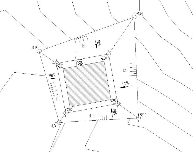
Figure 1
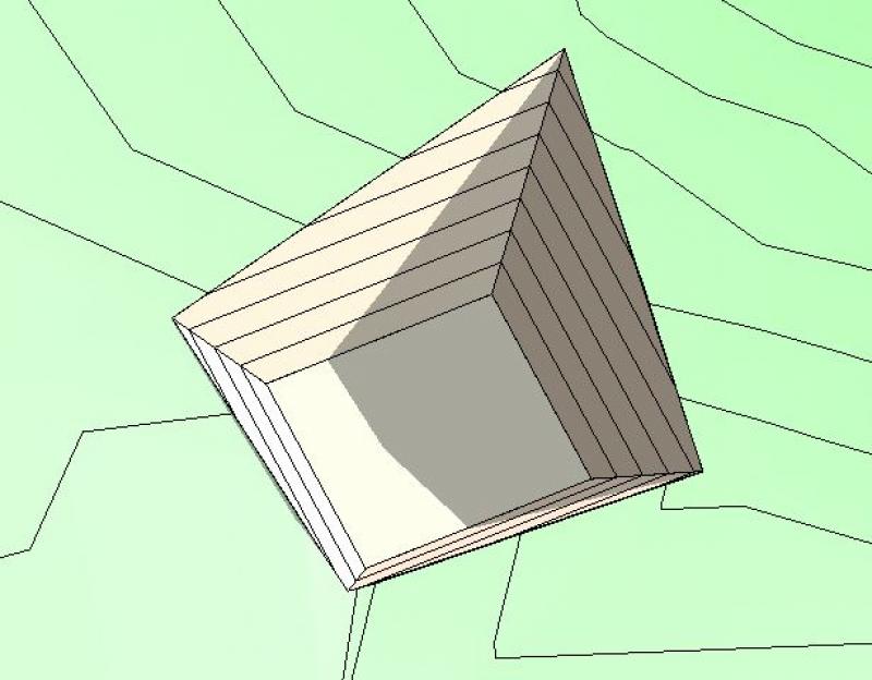
Figure 2
Features
During this phase, this object is created, and the necessary (geometric) features are generated through the modeling or creation of the object using the steps described below.
The following characteristics must be defined in this phase:
- General: Name (name of the excavation component)
- Generating: Geometry (building foundation elevations, slope gradients)
- Calculated: Volume (excavation volumes)
Labeling
The following labels are used for excavation work:
- Elevation points of building footings, slope edges
- Slope specifications
- Slope symbols
- Slope gradients
Â
- Elevation points: >Label >Elevation
- Slope information: >Label >Slope elevation
- To display slope symbols (short/long lines), you need to create special detail element families
- Slope gradients: >Label >Text
Instructions
In general, excavation modeling is performed by calculating the volume or mass of earth to be removed from a construction site (topography). To accurately determine the volume of earth to be moved, it is important to be able to provide mathematical or graphical verification.
For this reason, it is desirable to have a structured list of sub-volumes, which is the basis for the procedure described below.
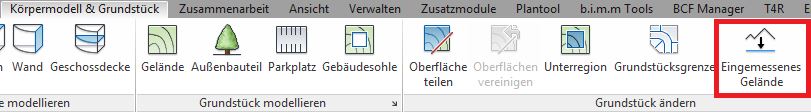
In Revit, the excavation volume is calculated based on the difference between two topographic models (existing and new) and is performed using the >Solid Model & Site and >Surveyed Terrain commands:
Overview
For general information on how to use the Open Space tool, please refer to the basic documentation provided by Graphisoft in the Help Center.
This documentation is based on the official template file "01 ArchiCAD 25 Template.tpl" from the ArchiCAD 25 AUT version.
The modeling and dimensioning of the excavation will be carried out after the existing terrain model has been completed in accordance with the surveyor's plan. Terrain/topography.
Usage
The creation of the terrain model for the excavation is carried out in several steps, as both the original terrain and the excavation must remain as two separate terrain geometries.
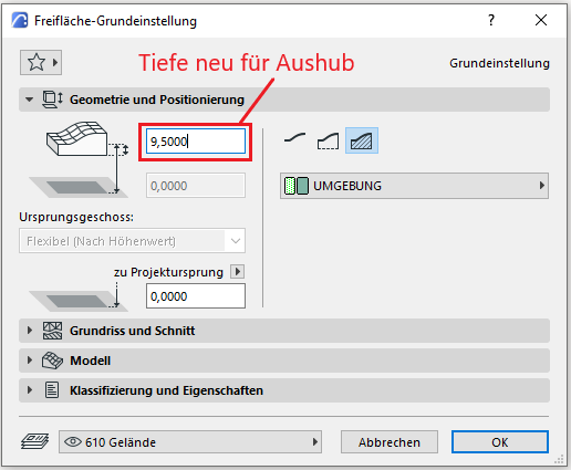
First, the existing terrain is duplicated. Next, one of the two open areas is set to “Demolition” in the conversion filter. This open area is now trimmed to the outer edges of the excavation (according to the building model specifications)—e.g., using the Split function. It is important that the already defined elevation points retain their Z-axis positions during this area reduction. Since this excavation geometry still has the same depth as the existing terrain, the excavation is now reduced in height:
As a result, the existing site now extends beneath the excavated area.
As a final step, the existing terrain must now be reduced by the volume of the excavation—this is done using the Solid Element command: The existing terrain is the target element, and the excavation is the operator. The subtraction is performed with upward extension.
No further measures regarding the excavation work are required at this stage.

Unfortunately, this content is available only to our Pro users.
If you'd like to read the full article, try the Pro account or become a Pro user.