In the construction industry, positioning in a Cartesian coordinate system refers to the mapping of a design into a georeferenced (geographic) coordinate system for surveying purposes using metric coordinates (north, east, and elevation). In German-speaking countries, for example, the Gauss-Krüger coordinate system is used for this purpose.
In general, BIM models can be created without Cartesian positioning; however, if required, it makes sense to establish this association at the start of the project.
Clients very often require that a construction project be mapped onto a Cartesian coordinate system—but planners would be well advised to avoid this at all costs and, if necessary, to negotiate the terms. What is the problem with this?
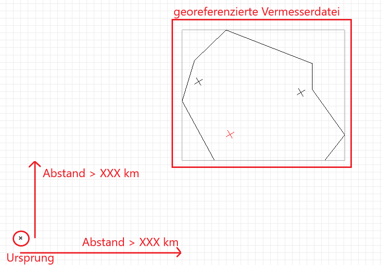
The geometric origin of a project can arguably be considered the most important coordinate in a digital building model—all other positions are referenced relative to it, and merging multiple sub-models (e.g., from different disciplines) also requires this central anchor point. The problem with using Cartesian coordinates as the project origin is that this origin can often be tens of thousands of kilometers away from one’s own property. This can lead to many problems—ranging from inconveniences when zooming and working in the model to geometric inaccuracies, e.g., when transferring model data to manufacturing machines such as milling machines or robots.
Positioning in a Cartesian coordinate system is performed at any stage of the planning process, depending on the project specifications. If specified by the client, this should be done as early as possible.
Features
In this phase, the object is positioned, and the necessary features are created by moving the object:
General:
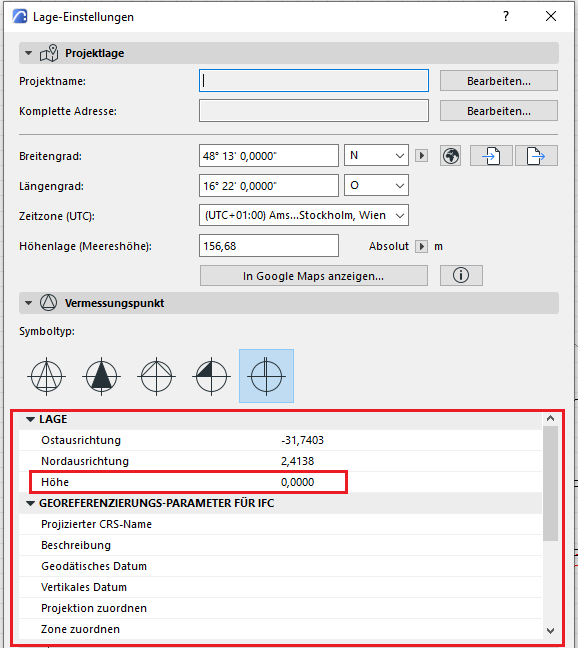
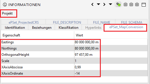
- North position
- East position
- Elevation
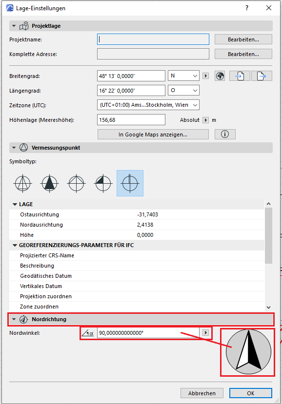
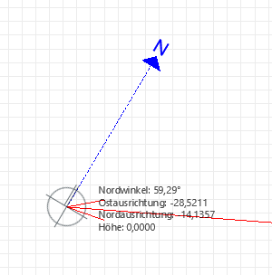
- Geographic north (angle to project north)
Instructions
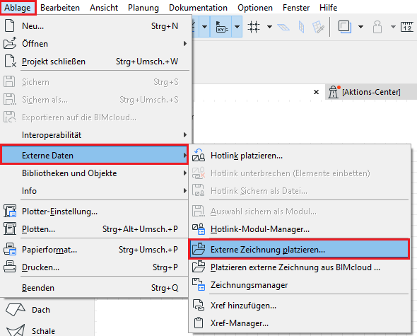
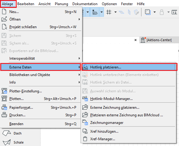
Generally, positioning is based on a surveyor's plan, which is typically provided as a north-oriented AutoCAD drawing and whose objects (cadastral boundaries and the like) are correctly positioned relative to the drawing origin in a Cartesian coordinate system. In this DWG, the location of the building in the property cadastre is defined by drawing building reference points.
To ensure correct positioning, the coordinates must first be transferred or imported from the surveyor's DWG file into a Revit file. By further transferring this coordinate data to the various Revit sub-models of a project, they are then placed on so-called shared coordinates—that is, on a consistent, common geographic location.
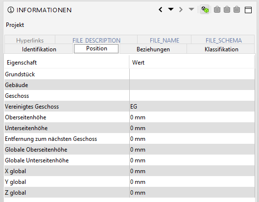
Overview of the Model Status in the Project
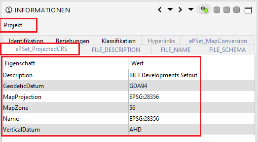
The Gauss-Krüger coordinate system (also known as the Cartesian coordinate system) serves as the basis for locating projects in relation to their actual positions.
Use of the Gauss-Krüger coordinate system
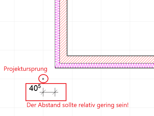
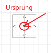
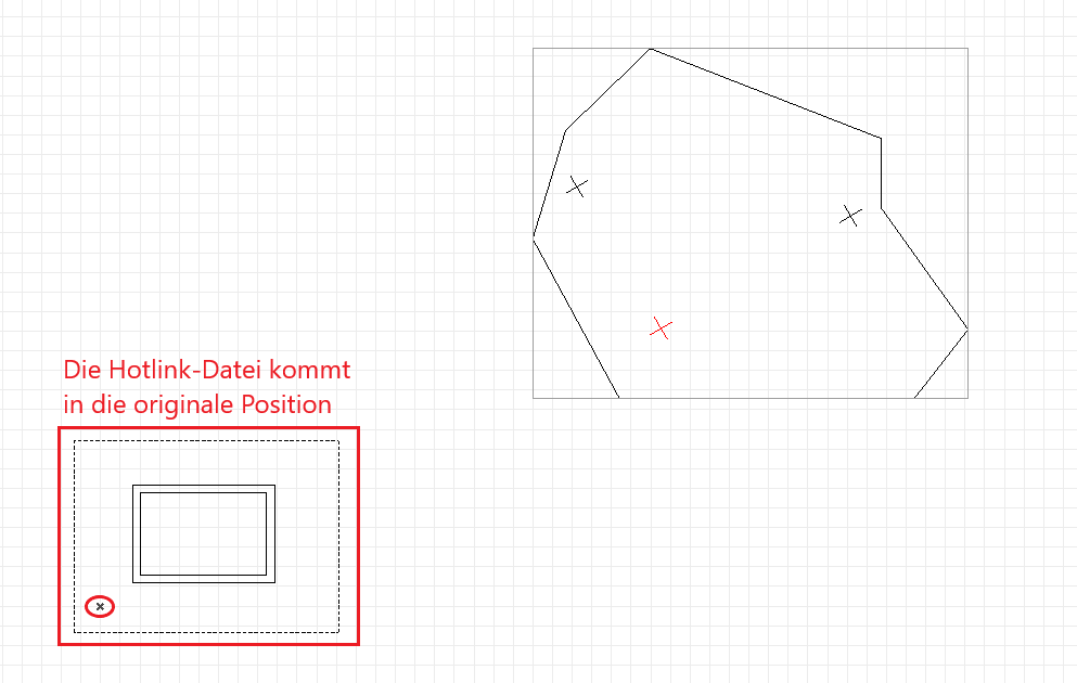
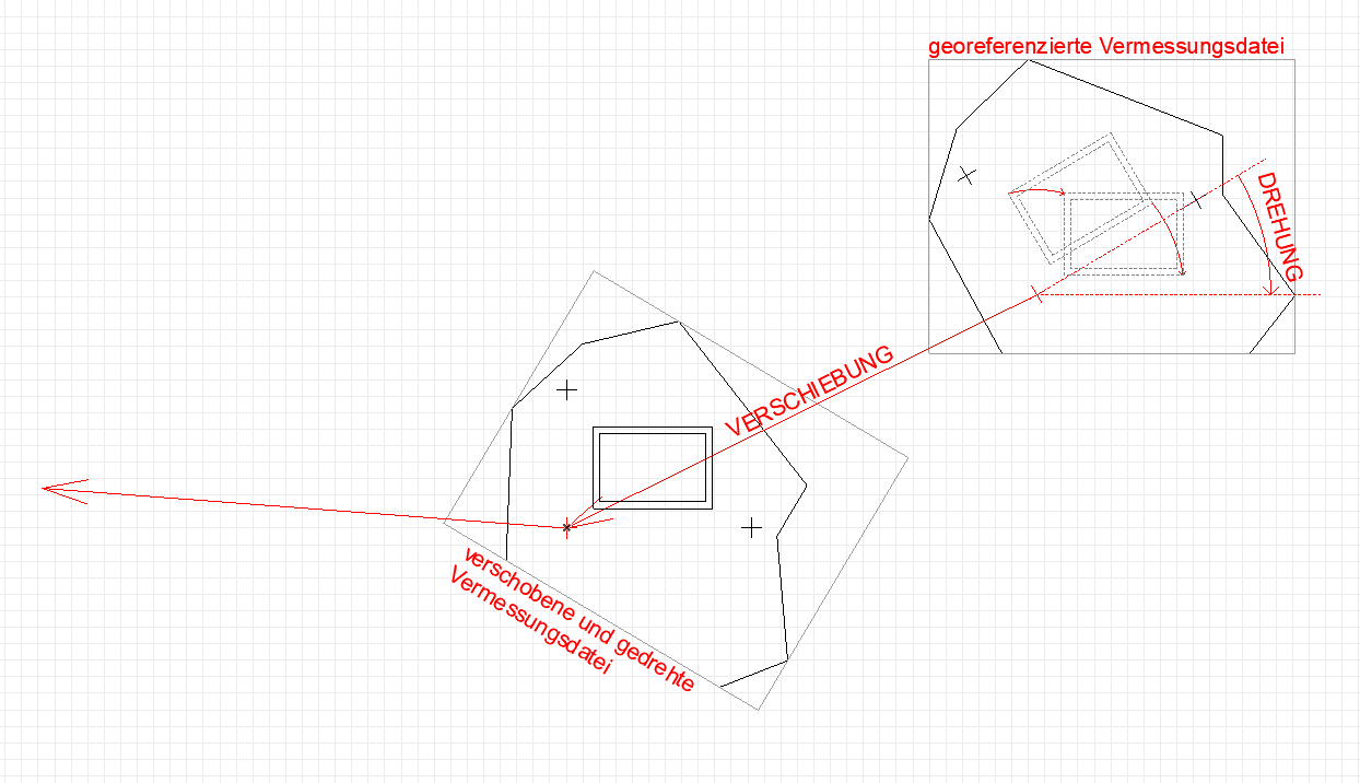
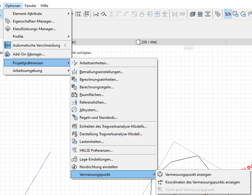
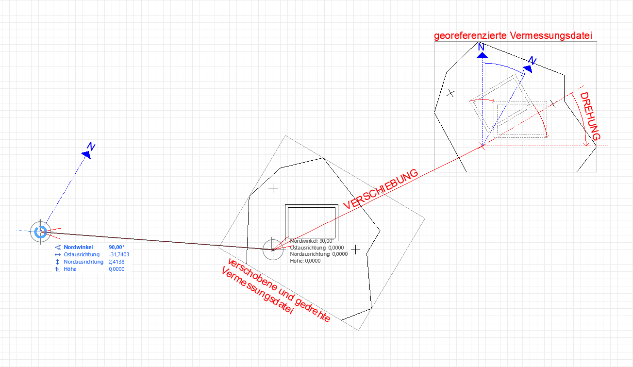
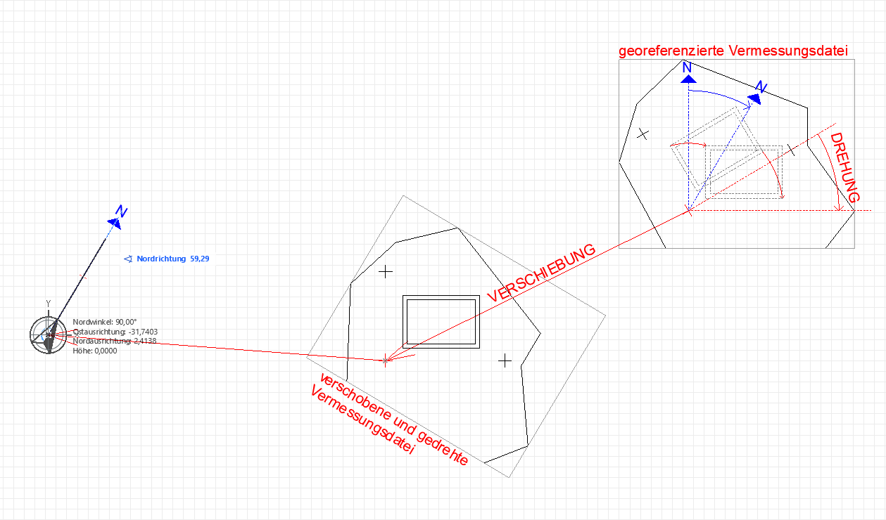
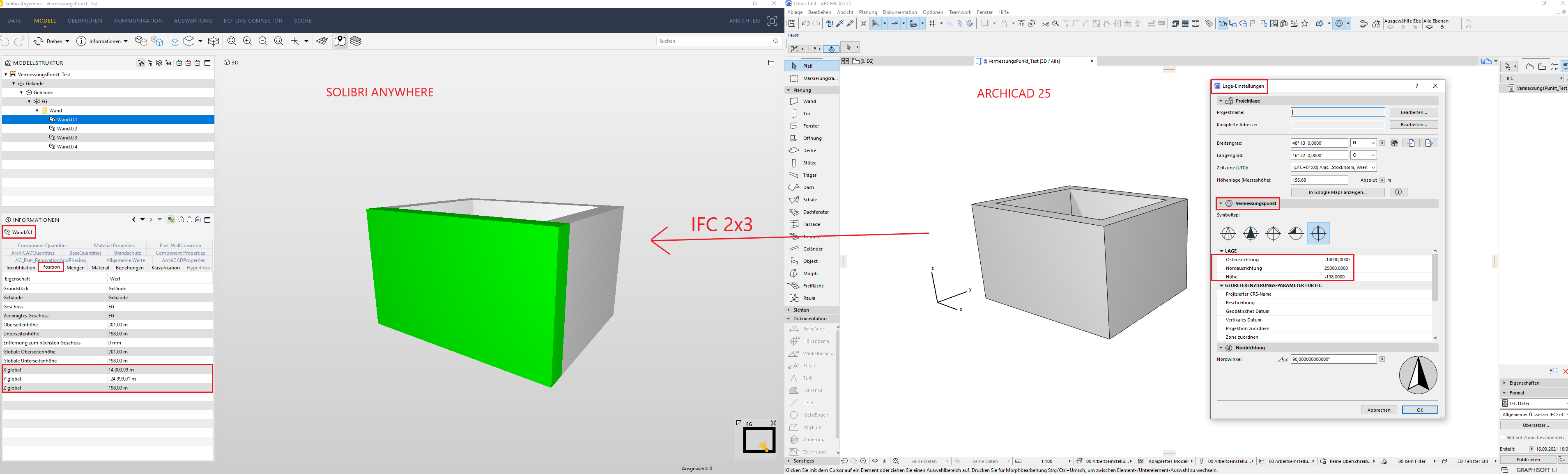
The project location is defined by inserting the three Gauss-Krüger reference points at their original positions. Since the data is shared with other project participants, a jointly defined project location is necessary. This means that the project model in ARCHICAD is not modeled at the ARCHICAD project origin (= x), but within the Gauss-Krüger coordinate system.
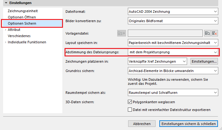
However, if modeling in ArchiCAD takes place far from the project origin, it is important to note that the project file enters a state known as “far from the origin,” which can lead to unwanted inaccuracies and, in some cases, software errors. This state is irreversible; therefore, we recommend the following if a file located according to the Gauss-Krüger coordinate system is required for IFC/DWG export.
- As usual, you will be working close to the ArchiCAD project origin in the "working file." The model should not be moved along the Z-axis.

If the project is being managed on the Autodesk Construction Cloud (ACC), please note the following information from Autodesk:
- The "Publish Current Shared Coordinate System" option is disabled for linked cloud-based collaboration files in Revit.
- However, you can still retrieve the shared coordinates.
For more information, see the following Autodesk article

Unfortunately, this content is available only to our Pro users.
If you'd like to read the full article, try the Pro account or become a Pro user.