In the construction industry, an elevator (or lift) is defined as a combination of a technical elevator system and the associated load-bearing enclosure structures. These consist primarily of the components of a shaft, within which the elevator car is guided, and its technically necessary extensions, which are referred to as the landing and the headroom.
This article primarily describes the structural implementation of elevator components in BIM. This includes the (structural) walls, floor slabs, and foundation slabs, as well as the representation of the key components of an elevator system, such as doors and the elevator car.
Some BIM programs offer specialized tools for modeling elevators, while in others, elevators are typically modeled from their individual components.
Search terms: elevator, lift, elevator shaft, access, access system
In this phase, the elevator components are modeled for the first time. It is not yet necessary to define materials (construction materials).
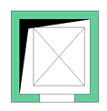
Presentation
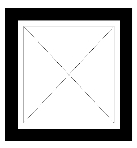
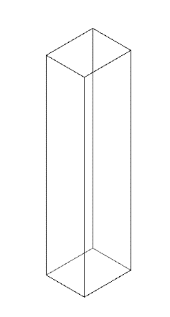
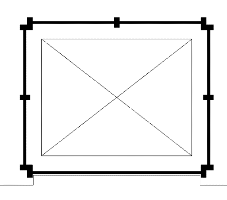
Floor plan
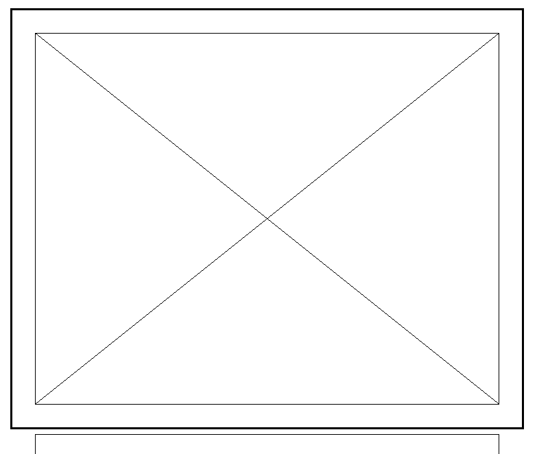
Cross-sectional view (not necessarily required at this stage)
Features
Labeling
At this stage, the component is not yet labeled or dimensioned in the plan views.
Instructions
While it is certainly possible to create families in Revit that could represent an elevator in its entirety, the many project-specific adjustments required for the headroom and pit areas lead most users to opt for modeling using individual components instead.
With regard to individual elevator components, a distinction is made between:
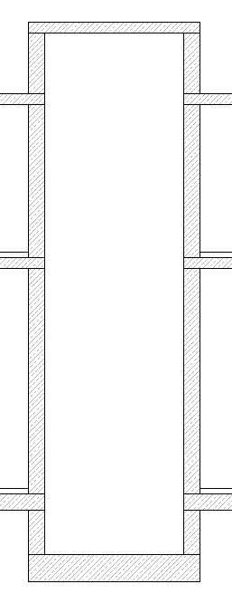
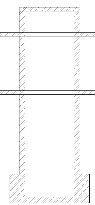
- Structural components: Shaft elements (walls, floor slabs, base slab), including the lower and upper sections
- Elevator system: Doors, elevator car
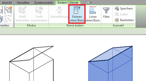
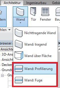
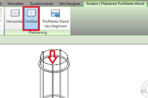
The structural components are created in Revit using load-bearing, single-skin walls, foundations, floor slabs, and openings (for instructions on how to create them, see the respective article link). The elevator system components are created using a special 2D element family for a simplified cabin representation, and the doors are created using a special door family to enable their inclusion in the door list if necessary.
In addition, the following should be taken into account:
- The bottom edge of the shaft walls is aligned with the top edge of the floor slab, and the top edge is aligned with the bottom edge of the floor slab.
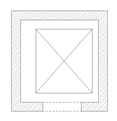
- The baseline of shaft walls is placed on the inside of the shaft.
- The floor slabs are aligned with the top edge in terms of height and extend across the elevator shaft; they are therefore modeled WITHOUT ceiling cutouts in the shaft area.
Overview
The basic modeling of elevators in ArchiCAD does not differ significantly across the various design phases; however, the amount of information (alphanumeric and detailed, as specified by requirements or the manufacturer) increases with each design phase.
An elevator, as an object spanning multiple floors, is placed using the object library. Within the object’s settings, the shaft wall surrounding the elevator car can be shown or hidden as desired. In early planning phases, detailed modeling of the shaft walls is not necessary, but only as long as the quantities/volumes of these walls do not need to be evaluated.
For general information on how to use the "Elevator" library element, please refer to the basic documentation provided by Graphisoft in the Help Center.
This documentation is based on the official template file 01 ARCHICAD 25 Template.tpl from the ARCHICAD 25 AUT version.
Building components classified as access structures are those necessary for providing access to a building; they are therefore defined as access elements.
First, select the floor to be used for the elevator/escalator 430 Elevator:
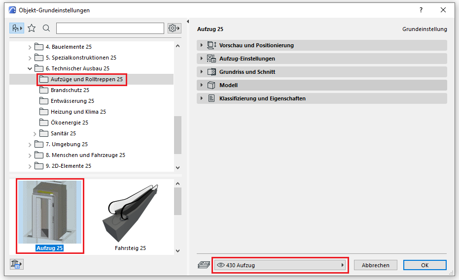
Preview and Positioning
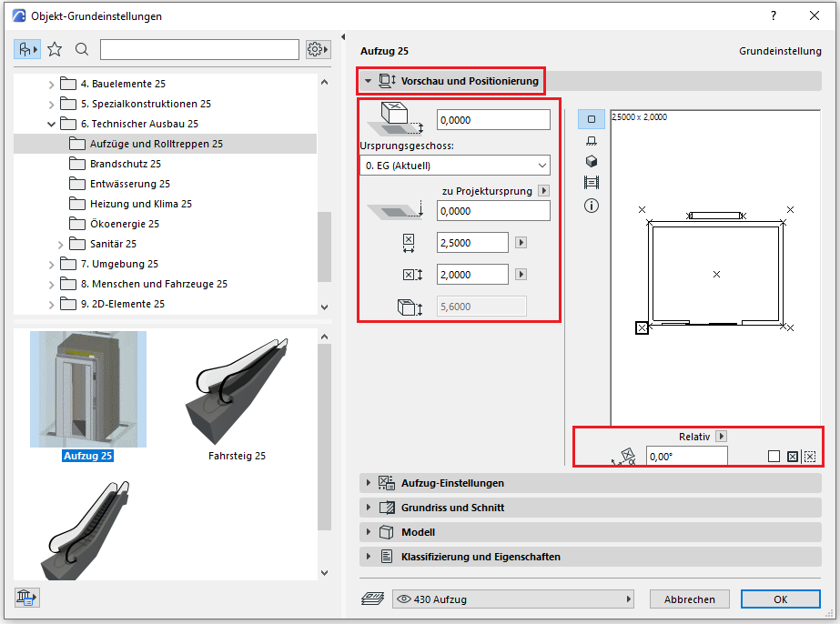
On this tab, you must specify the location relative to the ground floor, the dimensions, and the total height of the hoist.
Note: Since the elevator is the only building element that can be modeled across multiple floors, select the floor with ground-level access as the starting floor.
Settings
In the elevator settings (the same applies to escalators and moving walkways), the general settings regarding the shape, the number of door openings, and the position of the counterweight are first configured:
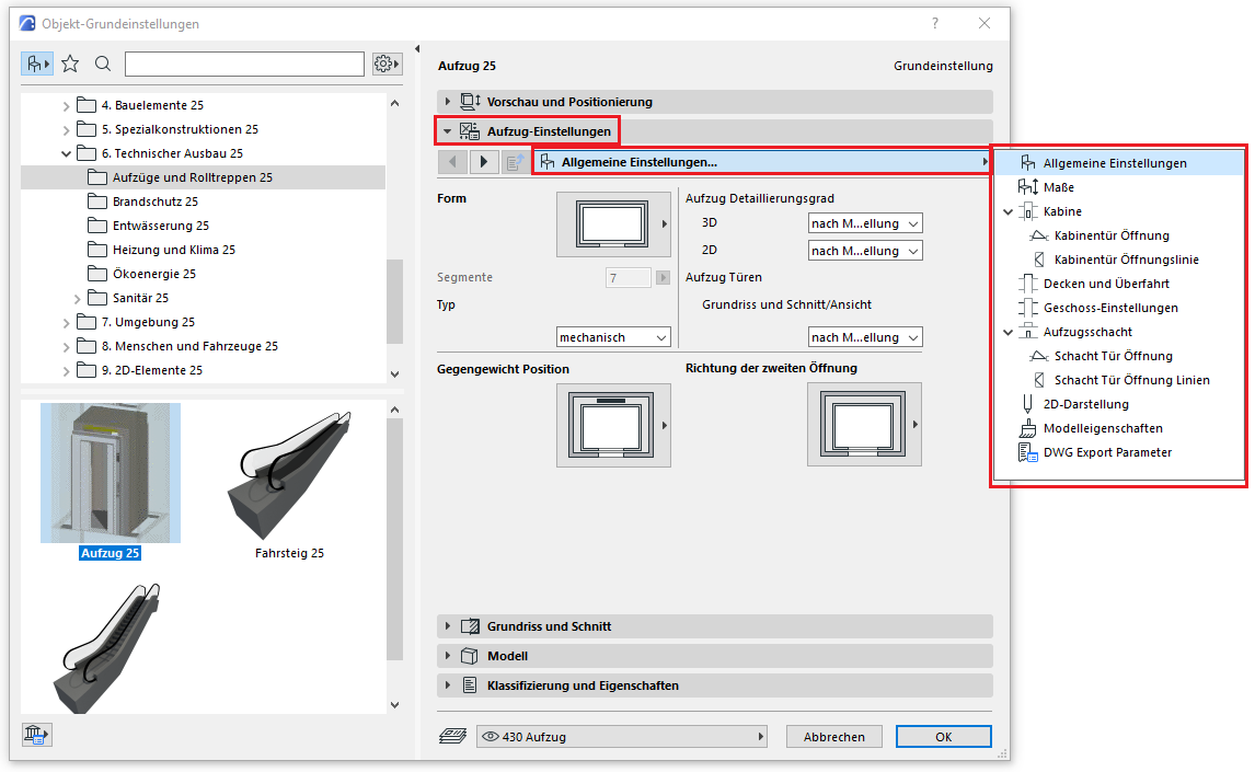
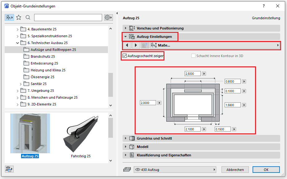
The dimensions defined earlier under "Preview and Positioning" are specified in detail:
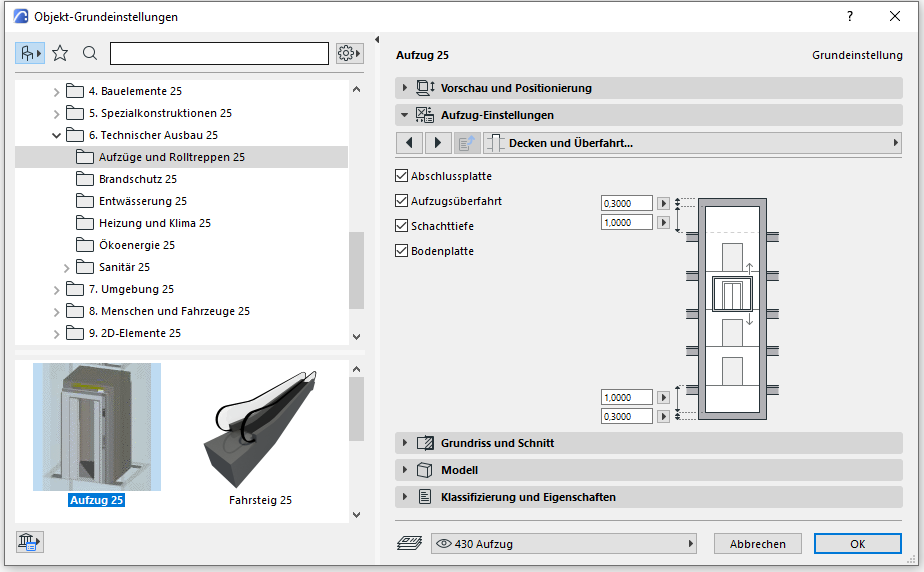
The following tabs similarly define the car doors, the upper and lower travel limits, the floors to be served (including any required intermediate stops in the form of split levels), as well as all necessary information for the floor plan and sectional views.
Floor plan and cross-section
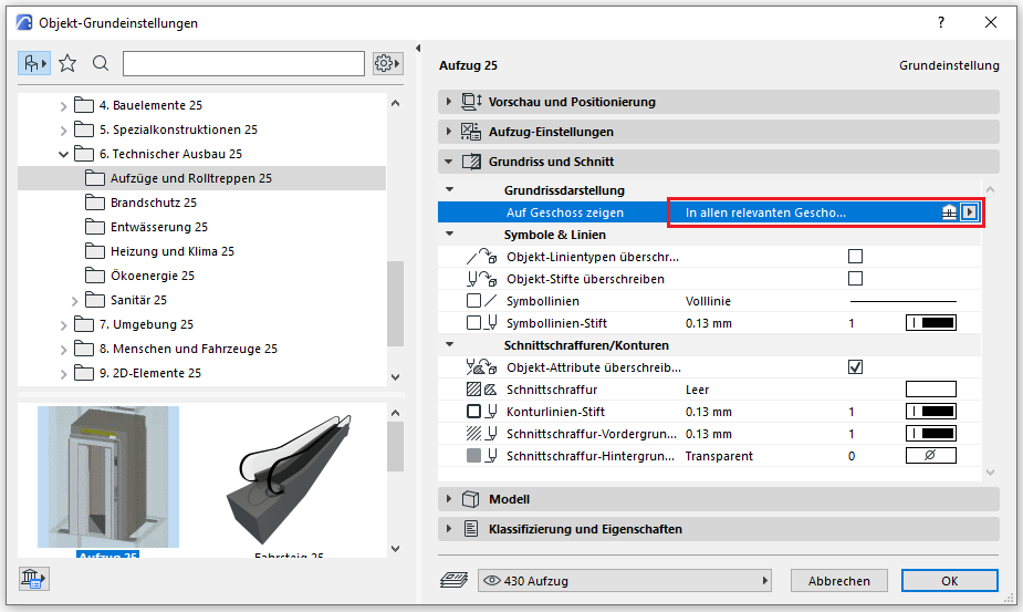
For floor-specific display, you must specify here on which floors the elevator should be displayed—since the elevator can be modeled across multiple floors, the option "All relevant floors" applies here.
Classification and Characteristics
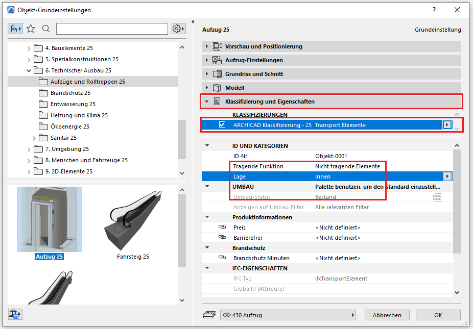
The element classification is the first definition in the Classification and Properties section—see also Classification. When you select a classification for a transport device, only those properties are displayed in the lower field area that are available for that classification according to IFC attributes.
The three properties that also serve a specific function within ArchiCAD are Load-Bearing, Location, and Renovation Status—these affect either the structural representation method, the envelope function (in other programs), or the renovation filter. All other attributes must be selected individually or determined in accordance with the project’s organizational guidelines (e.g., project manual or organizational manual).
During this phase, the materials (construction materials) and the load-bearing capacity of the structural components are determined.
Presentation
Floor plan
Cross-sectional view
Features
In this phase, the component is placed for the first time and automatically assigned geometric features.
Feature
- Stops
- Through-loading
- Number of passengers
Parameters
Outline Information
- Cabin width
- Cabin depth
Labeling
At this stage, the elevator is not yet labeled in the floor plans.
Instructions
Structural components of the elevator are load-bearing elements and should always be marked as load-bearing in the Properties window.
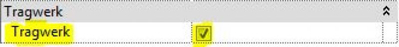
In addition, the calculation model should be enabled:

The basic process of modeling an elevator in ARCHICAD remains the same across the various design phases.
The new features and parameters added for this phase must be entered in the appropriate fields in the component's settings dialog.
The description of the settings dialog and the corresponding procedure can be found in an earlier section of this article.
The labeling and dimensioning of components should always be done associatively. Instructions on how to do this in ARCHICAD can be found in the relevant articles.
During this phase, information regarding structural design, building physics, and the basic technical data of the elevator system is added to the elevator components.
Presentation
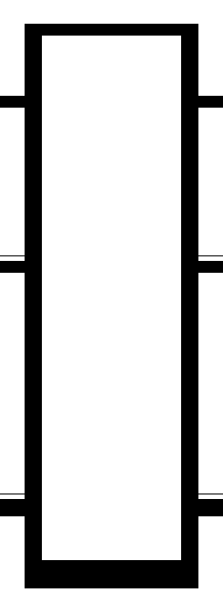
Cut
Floor plan
Floor plan (or with DB symbol)
TRWK
Cut
Floor plan
Floor plan (or with DB symbol)
TRWK
Cut
Floor plan
Floor plan (or with DB symbol)
TRWK
Features
Feature
- Fire department elevator
- Rated load
- Clearance
- Underpass
Parameters
- Shaft width
- Shaft depth
Outline Information
Labeling
During this phase, the components of an elevator are identified only in the structural design drawings.
- Load diagram: Load application
- Position diagram: Position
For labeling elevator structural components, use the labels from the following categories: walls (wall labels), floor slabs (floor slab labels), and foundations (foundation labels). These can be obtained from the Revit library.
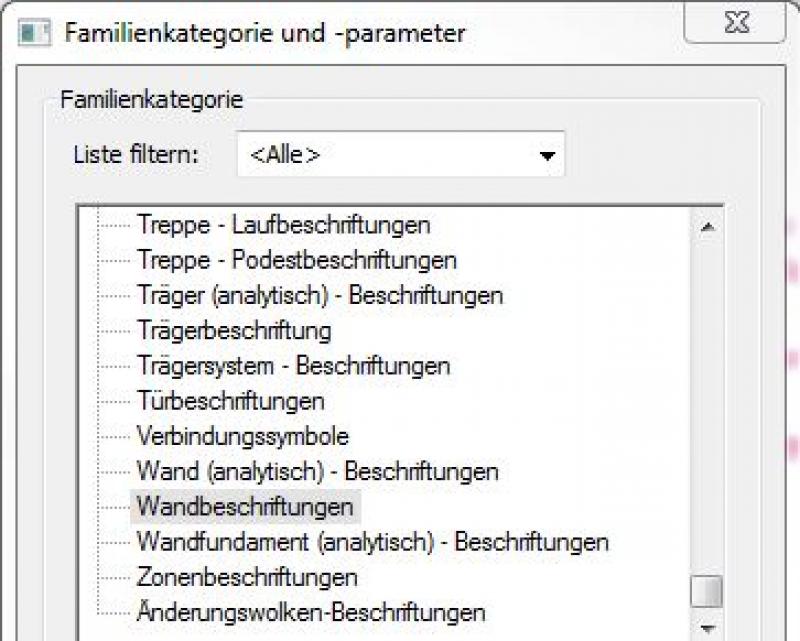
New labels can be created using the label family template >M_General Label. In the new family, the category should be set using the >Family Category and Parameters command:
For example, wall signage:
Instructions
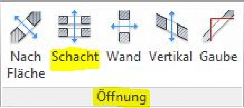
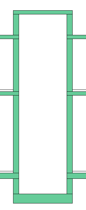
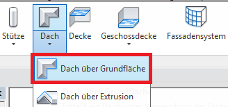
The openings for the floor slabs and the elevator shaft are created using the command >Architecture >Openings >Shaft and can be hidden as needed using filters.
The dimensions of the portal wall niches must be specified on the elevator door.
The basic process of modeling an elevator in ARCHICAD remains the same across the various design phases.
The new features and parameters added for this phase must be entered in the appropriate fields of the component's settings dialog.
The description of the settings dialog and the corresponding procedure can be found in an earlier section of this article.
The labeling and dimensioning of components should always be done associatively. Instructions on how to do this in ARCHICAD can be found in the relevant articles.
At this stage, at the latest, a further distinction is made between the various design options for structural components of elevators. For example, a distinction must be made between cast-in-place and precast floor slabs.
Presentation
This is where the different countries differ: In Austria, submission drawings are color-coded by building material; this classification is based on the reinforced concrete classification specified in the Vienna Building Code.
Cut
Floor plan
Floor plan (alternatively with DB symbol)
TRWK
Cut
Floor plan
Floor plan (or with DB symbol)
TRWK
Cut
Floor plan
Floor plan (or with DB symbol)
TRWK
Features
Labeling
During this phase, the architectural components of an elevator are labeled as "approval-ready."
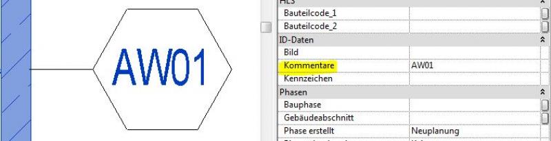
The components are labeled on the floor plan using their part numbers as listed in the parts catalog.
Example for the wall component: "AW01" or "IW01" (for exterior wall 01 or interior wall 01)
In addition, the net interior dimensions of the elevator are specified using a simple text entry.
Note:All structural types must be labeled manually and, if necessary, verified. This means that, ideally, labeling should be performed using a family that retrieves the necessary information from the parameters and properties of the structural components (see the example of a wall here).
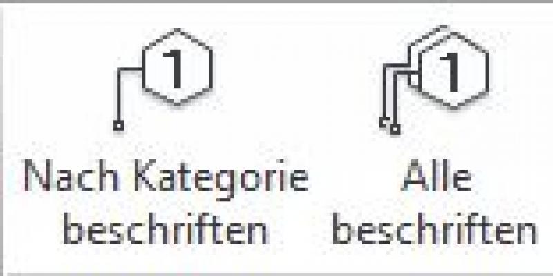
The commands for labeling are >Label >Label by Category or >Label All:
The labeling and dimensioning of components should always be done associatively. Instructions on how to do this in ARCHICAD can be found in the relevant articles.
Instructions
To ensure that building materials are displayed in the correct colors in accordance with Austrian building codes, a corresponding color scheme should be set to reflect the respective state standards.
Country-specific color settings:
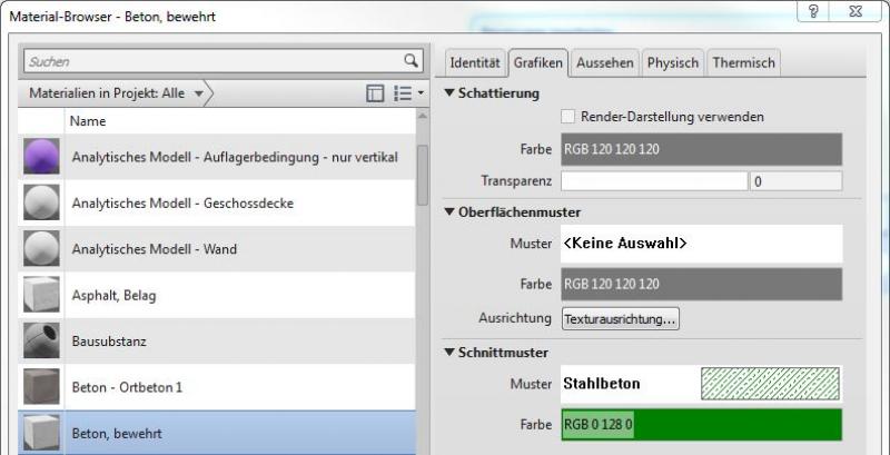
In Revit, the specific color schemes for submission drawings (permit drawings) can be defined in the material or type: Color in the type:
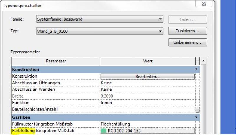
Color in the material:
The basic process of modeling an elevator in ARCHICAD remains the same across the various design phases.
The new features and parameters for this phase must be added in the appropriate sections of the component's settings dialog.
The description of the settings dialog and the corresponding procedure can be found in an earlier section of this article.
The labeling and dimensioning of components should always be done associatively. Instructions on how to do this in ARCHICAD can be found in the relevant articles.
During this phase, all information required for the procurement process (concrete grade, etc.) is added to the elevator components. In addition, the load-bearing components are reinforced. Depending on the collaboration scenario, this can be done in 3D within the component or separately from the model in 2D.
Presentation
Cut
Floor plan
Floor plan (alternatively with DB symbol)
TRWK
Features
Labeling
During this phase, all elevator components are fully labeled and marked with part numbers.
Architectural Floor Plan:
- Lower, upper, and front edges of foundation slabs; foundation slab thicknesses
- Slab bottom, top, and front edges; slab thicknesses
- Dimensioning of all wall edges
- Dimensioning of all built-in components
Structural Design Overview:
- Lower edge, upper edge of the slab
- Ceiling thicknesses
- Dimensioning of all wall edges
- All information relevant to the structural shell (built-in components, openings, etc.)
Instructions
The information regarding the reinforcement to be used in this phase must be provided by the structural engineering team and incorporated into the floor slab.
Further detailing of the elevator system can be achieved by customizing a corresponding detail element family, in which the desired representation can be created by inserting a DWG file provided by the elevator manufacturer.
The best way to label elevator structural components is to use a family that retrieves the necessary information from the components’ parameters and properties.For instructions on creating new families for wall, floor slab, and foundation labels, see the guide in this article under the section >Design >Labeling >Revit Workflow
The basic process of modeling an elevator in ARCHICAD remains the same across the various design phases.
The new features and parameters added for this phase must be entered in the appropriate fields in the component's settings dialog.
The description of the settings dialog and the corresponding procedure can be found in an earlier section of this article.
The labeling and dimensioning of components should always be done associatively. Instructions on how to do this in ARCHICAD can be found in the relevant articles.
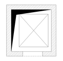
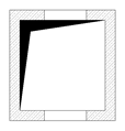
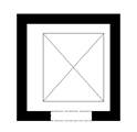
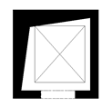
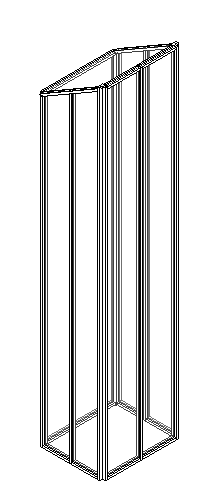
Presentation
Plan view
Model representation
Features
Labeling
During this phase, the elevator system components are supplemented with the manufacturer's specifications.
Instructions
Plan view
Model representation
img_08
img_10
img_12
img_14
The basic process of modeling an elevator in ARCHICAD remains the same across the various design phases.
The new features and parameters added for this phase must be entered in the appropriate fields in the component's settings dialog.
The description of the settings dialog and the corresponding procedure can be found in an earlier section of this article.
The labeling and dimensioning of components should always be done associatively. Instructions on how to do this in ARCHICAD can be found in the relevant articles.

Unfortunately, this content is available only to our Pro users.
If you'd like to read the full article, try the Pro account or become a Pro user.