Ramps are sloped structures used for vertical access. Depending on the construction type and geometry, modeling ramps can be quite challenging. For straight ramps, most programs use different element types to model ramps (despite the availability of specialized tools), e.g., sloped floor slabs in Revit or the roof tool in ArchiCAD. However, this modeling strategy quickly reaches its limits when dealing with curved ramps (in the floor plan)—in such cases, specialized objects are typically used. Structurally defined ramps, e.g., in steel or wood frame construction, are modeled from individual elements (e.g., columns and beams).
Like all load-bearing components of a building, structural ramps serve as an interface between architecture and structural engineering. If a model-based data transfer to structural analysis software is planned, it may be necessary to use specific modeling methods tailored to the particular software configuration.
Search terms: driveway, exit, access road, access ramp, accessible, overcome
In this phase, the ramp is constructed, but no decision regarding the material has been made yet.
Presentation

Plan view
Model representation
Features
Feature
- Status
Parameters
Outline Information
- Exterior element
- Room-enclosing element
Labeling
In this phase, ramps are not yet labeled in plan views.
Instructions
Ramps can be created in Revit using the >Architecture >Ramp command.
Overview
The basic process of modeling ramps in ArchiCAD does not differ significantly across the various design phases; however, the amount of information (both alphanumeric and detailed) increases with each phase.
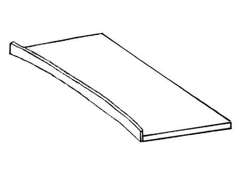
A ramp is placed on its starting floor (i.e., the floor where the ramp begins) and can also be created as a custom shape.
For general information on how to use the "Ramp" library element, please refer to the basic documentation provided by Graphisoft in the Help Center.
This documentation is based on the official template file 01 ARCHICAD 25 Template.tpl from the ARCHICAD 25 AUT version.
Elements classified as ramps are elements necessary for providing access to a structure > they are therefore defined as access elements.
A ramp can be created using a library element, the Staircase planning tool with the "Select" option (set the selection to "Ramp"), or the Roof Surfaces tool. The individual settings dialogs for a ramp vary depending on the library element type or whether it is created individually using the planning tool. For the construction, the settings dialogs of the Roof Surfaces tool apply.
In general, however, all ramps are:
- Accessibility features and
- to be modeled on a floor-by-floor basis.
It is always positioned in the
- Starting point (= ramp entry),
and their display depends on visibility
- Only on the ground floor or
- the original floor and the floor above it
Set separately (2D icon > Floor-dependent on/off > 2D above origin floor).
First, select the floor for the ramp: 40-step ramp:
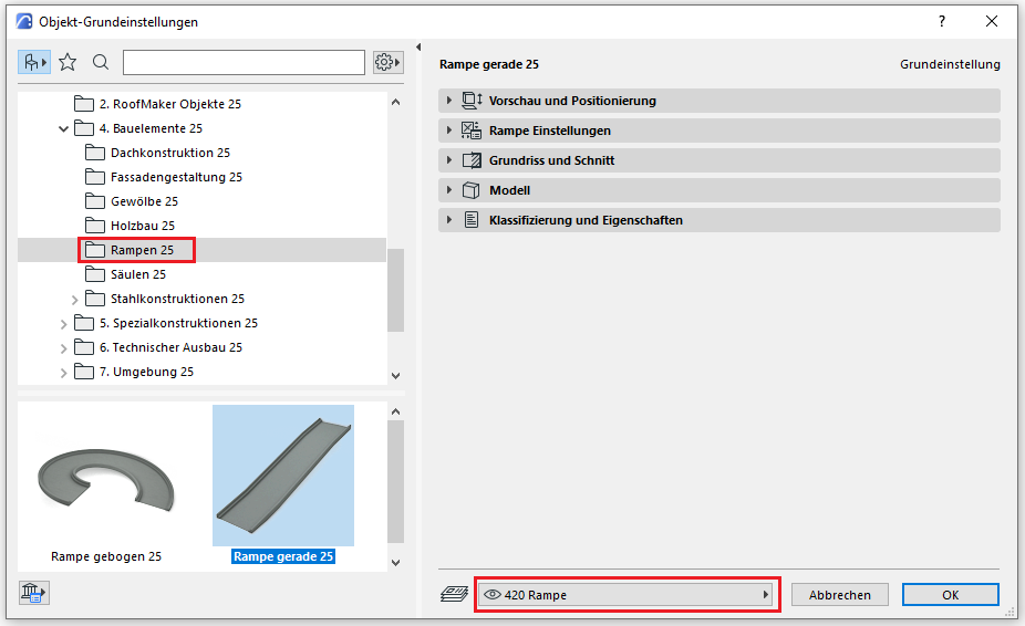
Using the Ramp library element:
Preview and Positioning
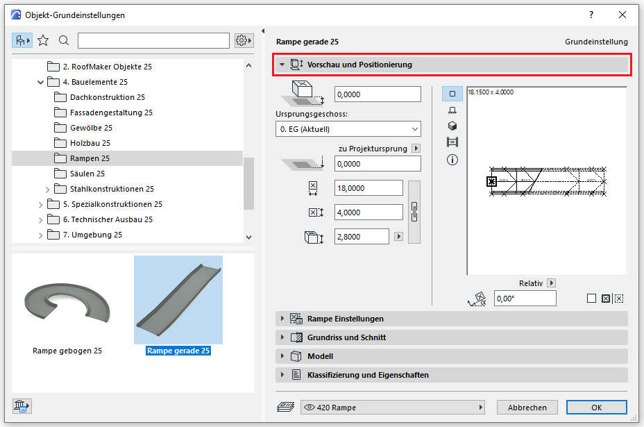
On this tab, you must specify the position relative to the ground floor (e.g., for ramps with a separate landing), the dimensions, and the total height of the ramp.
Settings
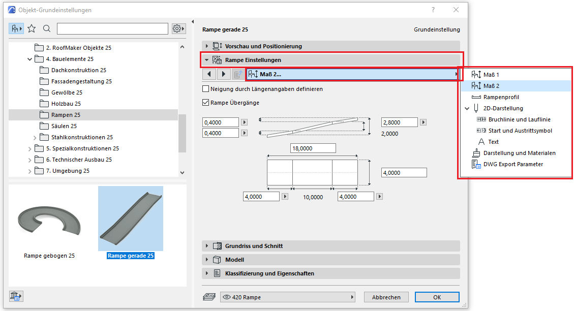
In the ramp settings, you first specify the dimensions, the ramp profile, the 2D display, and the ramp labeling. The break line for a floor-dependent display is also defined here (applicable for the floor plan view "Base floor and one floor above").
Floor plan and cross-section
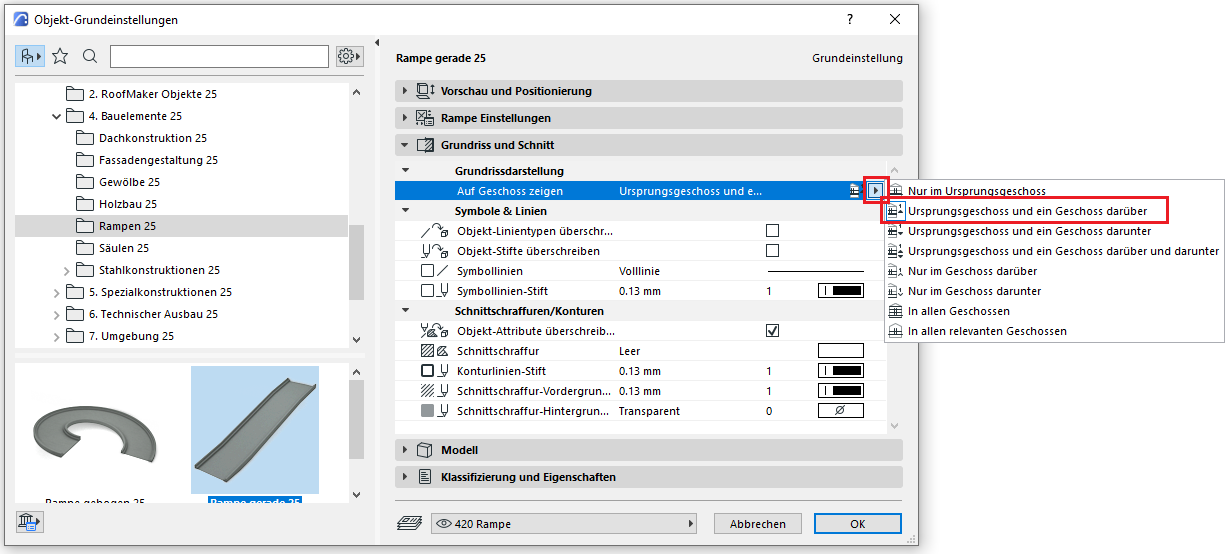
For floor-specific display, specify here on which floors the ramp should be shown; see also Ramp Settings/2D Display.
Classifications and Characteristics
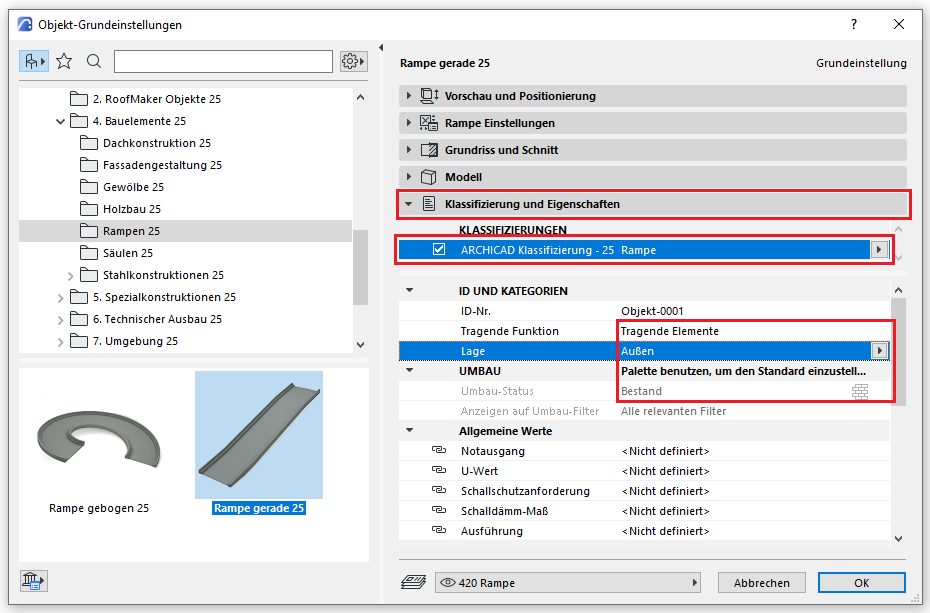
The element classification is the first definition in the Classifications and Properties section—see also Classification. When you select a classification in the drop-down menu, only those properties available for that classification according to IFC attributes are displayed in the lower field area.
The three properties that also serve additional functions within ARCHICAD are Load-Bearing, Location, and Renovation Status—these affect either the structural representation method, the envelope function (in other programs), or the renovation filter. All other attributes must be selected individually or determined in accordance with the project’s organizational guidelines (e.g., project manual or organizational manual).
Alternative
Create a ramp using the Roof Surface or Morph tool:
For example, if we model a ramp with a structure for an underground garage exit, we can also create it using the Roof Surface or Morph tool. In this case, all the settings dialog descriptions for this tool apply.
Note: When using this design method, make sure to assign the classification to the ramp rather than the roof, so that all the necessary attributes for this building element are available under "Categories" and "Properties."
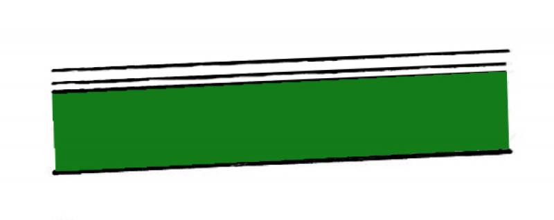
During this phase, materials are assigned to the ramps and further detailing is carried out.
The basic process for modeling a ramp in ARCHICAD remains the same across the various design phases.
The new features and parameters for this phase must be added in the appropriate sections of the component's settings dialog.
The description of the settings dialog and the corresponding procedure can be found in an earlier section of this article.
The labeling and dimensioning of components should always be done associatively. Instructions on how to do this in ARCHICAD can be found in the relevant articles.
Presentation
Plan view
Model representation
Features
- accessible
- Fire resistance class
- Escape route
- Flooring
- Custom ramp run
- Straight ramp
- Spiral ramp
- Undefined ramp
- Tread depth
- Clear width
- Slope
Labeling
At this stage, ramps do not yet need to be labeled in plan views.
Instructions
The basic process for modeling a ramp in ARCHICAD remains the same across the various design phases.
The new features and parameters added for this phase must be entered in the appropriate fields in the component's settings dialog.
The description of the settings dialog and the corresponding procedure can be found in an earlier section of this article.
The labeling and dimensioning of components should always be done associatively. Instructions on how to do this in ARCHICAD can be found in the relevant articles.
During this phase of planning, the ramps are supplemented with structural engineering data, and further detailing is carried out. As part of this process, the ramp’s structure is defined and the curb (or wheel stop) is added.
Presentation
Plan view
Model representation
Features
Feature
- Route
Labeling
During this phase, ramps are labeled only in the structural drawings. This involves creating a label for the load application in the load schedule and a label for the location in the location schedule.
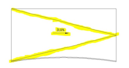
On the architectural drawing, the slope must be labeled with an arrow and a percentage. In addition, the direction of the slope must be indicated using 2D lines (model lines).
Instructions
The TWP information must be provided as examples for the objects. This information is required for the load plans and location plans. The TWP is responsible for entering this information.
In this phase, the ramp structure is also defined; it is modeled as a separate floor slab (multi-layer).
During this phase of planning, building physics data is incorporated into the project. This includes information related to fire safety.
The floor plan
Presentation

Features
Labeling
During this phase, the component is labeled only in the TWP drawings. This involves creating a label for the load application in the load schedule and a label for the location in the location schedule.
On the architectural drawings, the slope must be labeled with an arrow and a percentage. The direction of the slope must also be indicated using 2D lines (model lines).

Instructions
The information provided by the building physics team must be incorporated into the model by the architecture team.
When distinguishing between precast and cast-in-place concrete components, the renaming of the type and the differences in material must be taken into account.
During this phase, the drawings are supplemented with all information regarding the reinforcement, as well as the information required for the contract award (concrete grade, etc.).
Presentation

Plan view
Model representation
Features
Feature
- Reference
Parameters
- Gross area of the ramp
- Gross volume of ramp run
- Ramp slab thickness
- Counter-slope
- Length
- Net area of ramp run
- Net volume of ramp run
Outline Information
Labeling
The following labels are available for ramps:
Instructions
The information regarding the reinforcement to be determined during this phase must be provided by the TWP and incorporated into the floor slab.

Unfortunately, this content is available only to our Pro users.
If you'd like to read the full article, try the Pro account or become a Pro user.