By definition, BIM project models are single-object-based, data-rich 3D building models.
Virtual 3D objects, such as walls, windows, or columns, are assigned alphanumeric information that describes their properties. In addition, the geometric representation of these component objects can be controlled using parameters.
As the project progresses through the planning phases, the level of detail of these building elements increases—more and more information is added, and more and more properties are defined. The level of geometric detail also increases over time, for example, to enable more detailed graphical representations in drawings. In this context, we refer to the so-called phase model.
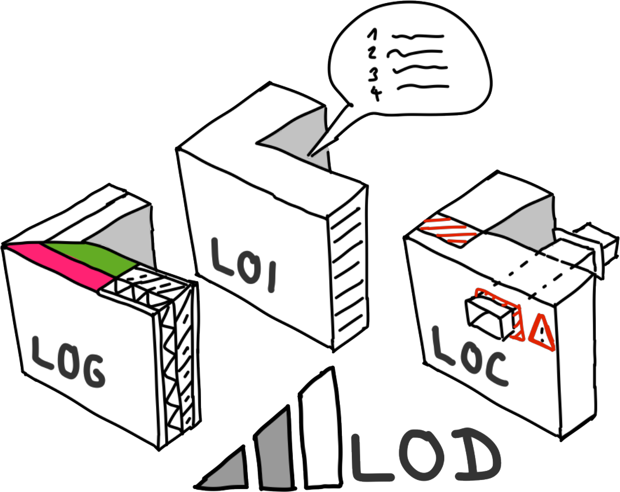
Internationally, the maturity level of a virtual component object (as well as the resulting partial or complete model) is referred to as the Level of Development, or LOD for short. It consists of three indicators, which are explained below.
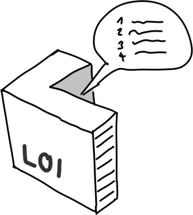
This indicator describes the alphanumeric level of information maturity for virtual building components. As each planning phase progresses, more and more properties are defined until, ultimately, all the information required to construct the element is available. After construction (provided that so-called as-built documentation is available), additional information necessary for operation is usually added, meaning that the LoI continues to rise even after completion.

This indicator describes the geometric level of detail of virtual components. Internationally, it is typically specified in increments of 100, ranging from LoG 100 to LoG 500, and illustrated with corresponding symbols. Intermediate levels (e.g., LoG 350) are less common. The term "Level of Detail," which was previously in use, was replaced by "Level of Development" to avoid ambiguity caused by the abbreviation.
LoG requirements are typically formulated either in general terms as client information requirements or on a project-specific basis in BIM implementation plans. Unfortunately, however, such requirements are rarely sufficient to provide truly useful definitions of just how detailed the modeling should actually be. The following figure illustrates how the internationally accepted LoG definition relates to the scale and service phase specifications more commonly used in German-speaking countries:
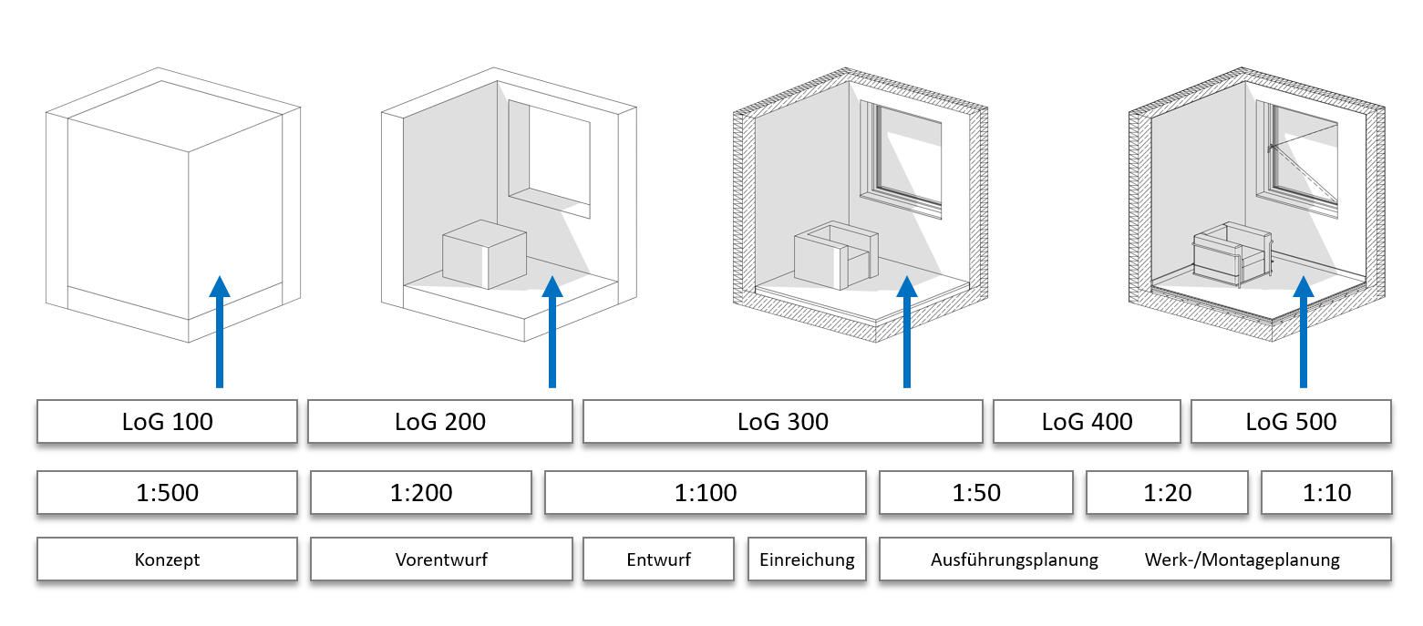
The lack of clarity between LoG, scale, and phase described here can be explained by the fact that LoG definitions are often provided (as shown above) only in the form of example images (leaving considerable room for interpretation).
It should be noted that, in terms of modeling, construction detailing rarely goes beyond LoG 300 and the resulting 1:50 scale. This is where the best cost-benefit ratio between modeling effort and information gained is achieved. Higher planning scales, such as detailed drawings, are commonly produced by planners as 2D drawings (largely decoupled from the model). Construction and installation planning, on the other hand, typically operates in the LoG 400–500 range (depending on the trade). However, the resulting geometric load of the models quickly pushes large projects to the performance limits of standard CAD workstations and therefore represents a critical factor in interdisciplinary coordination.
Tip
If such requirements are specified in a project (e.g., by the client), it is advisable to carefully review the requirements and clarify any details at the start of the project. Especially when the LoG exceeds 300, modeling can become very time-consuming and may also lead to critical performance issues in larger projects. Modeling beyond LoG 300 is generally not recommended.
Unless explicit guidelines are provided for a project, we recommend using the LoG definitions on BIMpedia; see the next section.
The LoG on BIMpedia
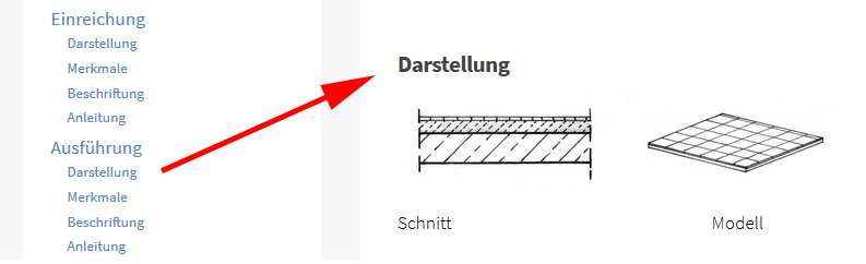
In our modeling guides, you will find an example LoG representation for each project phase for all elements in building construction. Please refer to the links in each chapter for the representation for each phase.
Background: Why LoG?
Especially on large projects, the CAD workstations typically used in construction planning can easily reach their capacity limits: Tens of thousands of highly detailed 3D elements still overwhelm even today’s graphics cards, and network loading times and CPU background calculations for the graphical display of models and other content can also create a bottleneck. The trend is therefore toward sub-elements with as little detail as possible—as much geometric detail as is necessary, for example, for a plan view, but as little as possible. Instead, the level of information is increased.
The illustration below shows an example of this: To determine which office chair should be used in my project, all I need is a 3D dummy object containing the relevant information—specifically, that it is a Type X chair from Manufacturer Y.
Unfortunately, it is still common—especially among manufacturers—to offer BIM objects with an almost absurd level of detail on various platforms, which can lead to serious performance issues in large-scale projects.
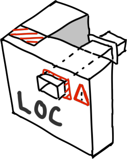
The LoC indicates the degree of coordination of virtual components. Is an object collision-free, barrier-free, and suitable for assembly and maintenance? Depending on the type of model review conducted as part of quality management measures, conspicuous elements are flagged as problematic. Only when all elements of a partial or complete model are classified as non-critical is the Level of Coordination deemed sufficient for production readiness.
Finally, the LOD defines the overall maturity level of a virtual component. It is composed of the sub-indicators described above.
Similar to the phase model, LOD model checks can thus be used to answer the following questions:
- LoI: Have all the required properties for each building element been defined for this phase?
- LoG: Is the object detailed enough to allow me to derive a standard-compliant 2D representation and ensure a high-performance 3D representation?
- LoC: Is the object free of collisions, and are installation and maintenance clearances maintained?
Similar to LoG, LOD is generally specified internationally in increments of 100, e.g., LOD 100, LOD 200, LOD 300, LOD 400, LOD 500. Intermediate levels (e.g., LOD 350) are less common.