In the construction industry, “surrounding buildings” refers to existing structures in the vicinity of a construction project that are of only minor importance for the construction design. In the BIM workflow, the structure of these buildings—also referred to as existing buildings—is typically reduced to simple geometric shapes in order to quickly generate a graphical representation of the urban context.
In a BIM model, surrounding buildings are created either by placing pre-made standard objects or by generating composite objects.
Keywords: inventory, neighbor, surroundings, house, environment, connection, old, construction, building
At this stage, surrounding buildings are not yet rendered as 3D objects but are represented solely as 2D surfaces in order to identify buildings and open areas using the simplest possible methods.
Presentation
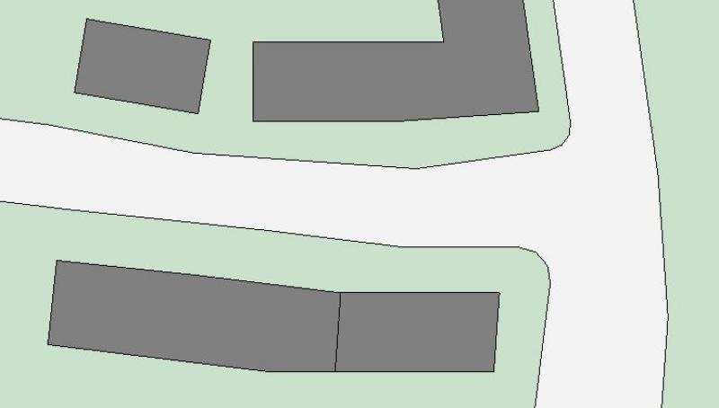
Plan view: Floor plan only, as 3D modeling is not yet being used at this stage.
Features
In this phase, these objects are represented only in 2D, and the required features are created by drawing surfaces. The following features are defined in this phase:
- General: Name of the area (e.g., existing buildings)
- Generator: Boundary of the area
Labeling
In this phase, the 2D surfaces are labeled.

Face text families can be selected from Autodesk Content and loaded into the project.
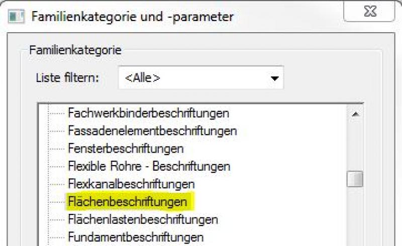
If the desired label does not yet exist, you can create a new label family using the M_General Label template. When doing so, change the category to Area Labels:
The basic process of modeling a room surface in ARCHICAD remains the same across the various design phases and whether the space is interior or exterior. A detailed description of the Room Surface tool can be found in the article "Room."
Instructions
Existing buildings are created in this phase by drawing 2D surfaces.
For more information on creating area plans, see the article "Areas and Zones."
Before creating areas, a special floor plan—known as an area plan—should be drawn up, on which the area boundaries and, finally, the areas themselves are marked.
- Command for creating a floor plan:
>Architecture >Floor Plan >Floor Plan or >View >Top Views >Floor Plan
- Command for creating area boundaries:
>Architecture >Land Use Restrictions

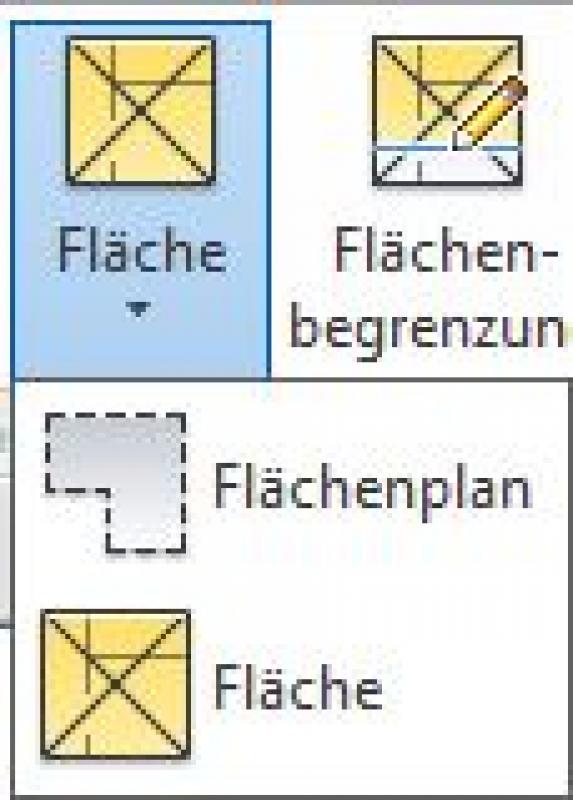
- Command for creating surfaces:
>Architecture >Spaces >Spaces
No further significant measures will be taken regarding the surrounding buildings at this stage.
In this phase, surrounding buildings are modeled in 3D for the first time.
Presentation
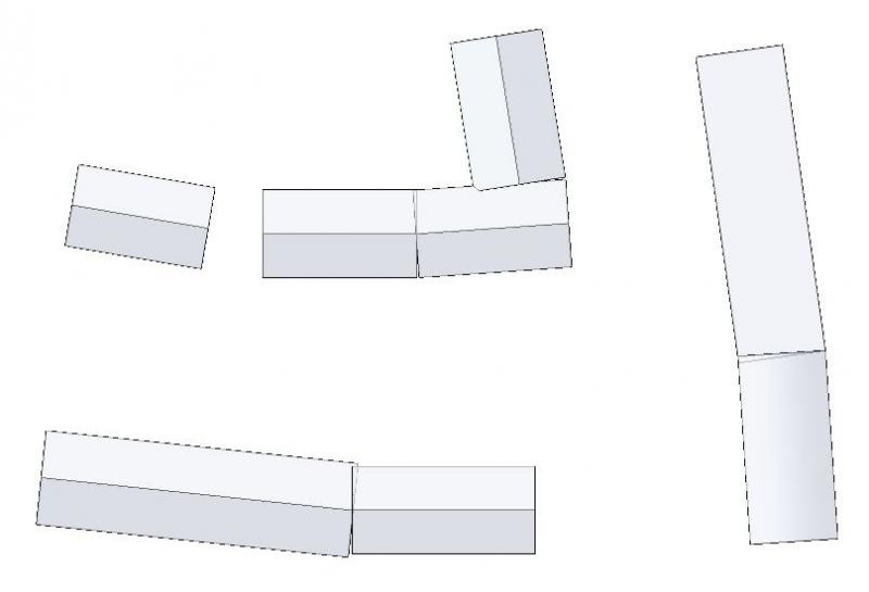
Figure 1
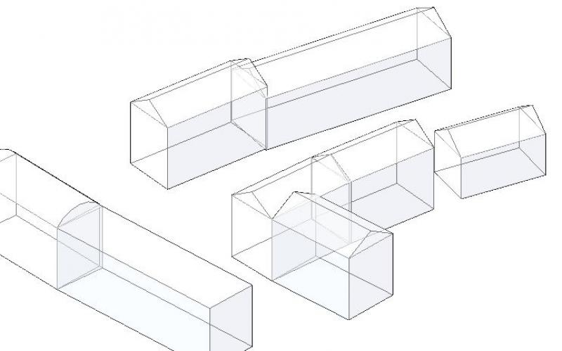
Figure 2
Features
Apart from the geometry and location of the buildings, which are determined by the modeling, no other significant features are required. The following features may also be defined at this stage:
- Generator: Main elevations of building roofs (if necessary)
Labeling
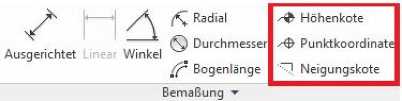
The labeling is done using elevation marks.
In ARCHICAD, the system for labeling and dimensioning adjacent buildings in floor plans, sections, and elevations is always element-based (adaptive), with the exception of custom text.
The labeling and dimensioning of the component should always be done associatively. Instructions on how to do this in ARCHICAD can be found in the relevant articles.
Instructions
There are essentially two ways to create solids in Revit that can be used for this purpose.
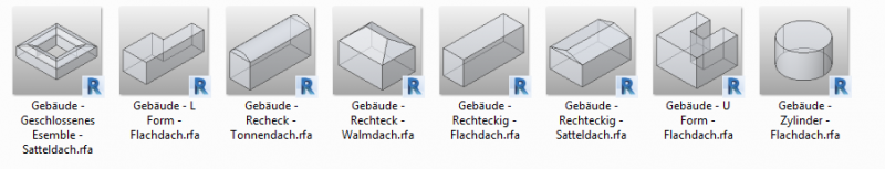
Standard body
For regular and simple shapes, the Revit Autodesk Content library under "Solids" (...\\Libraries\\Germany\\Solids) offers various standard building models whose dimensions can be adjusted parametrically:
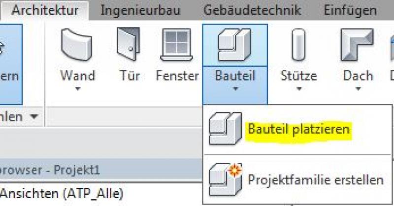
To place these pre-made families, use the command >Architecture >Component:
By default, the "Solids" category is disabled in Revit, which is why these buildings are often not visible. In this case, you should enable the "Solids" category under Visibility.
Composite bodies
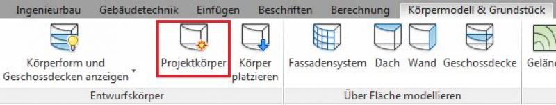
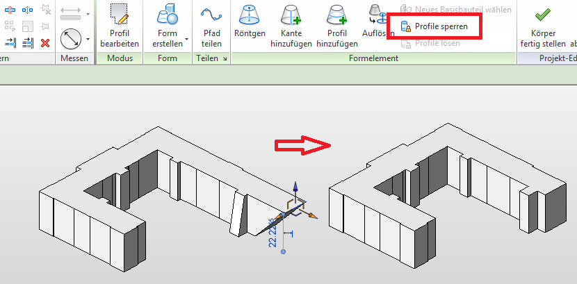
To create both simple and complex solids, use the command >Solid Model & Site >Project Solid:
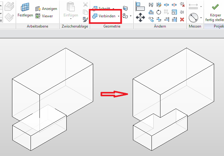
Complex buildings (e.g., consisting of structures of varying heights) are modeled in multiple parts within a project body and then joined using the command >Modify >Join >Join Geometry.
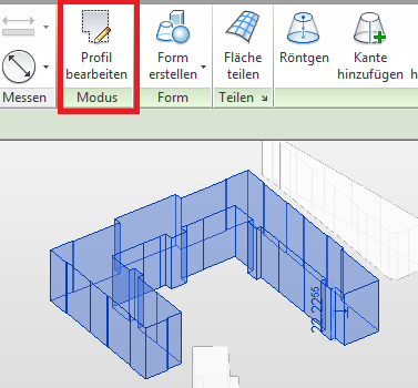
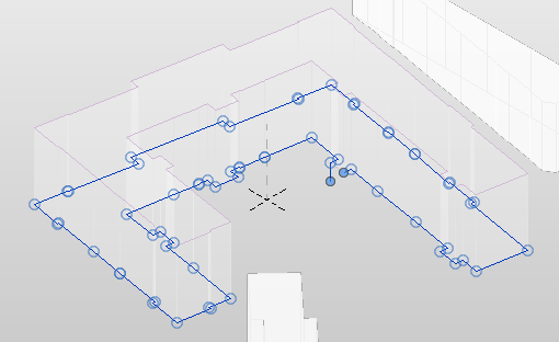
To change the base area, use the >Edit Project Solid command and then select the solid. You can change the base area using >Edit Profile.
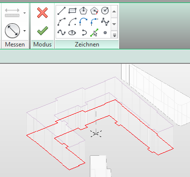
Clicking >Lock Profiles will realign all vertical surfaces to be perpendicular.
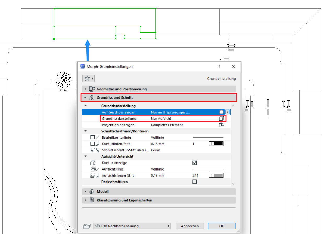
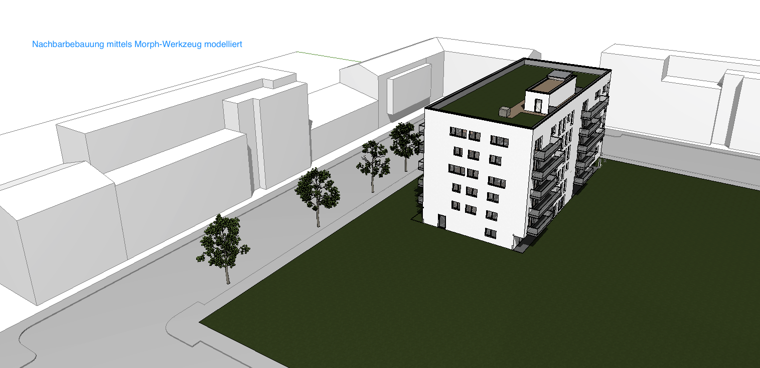
The surrounding buildings are modeled using the Morph tool—data is incorporated based on the surveyor's plan, zoning plan, etc.
Neighboring buildings are modeled at the 630-meter elevation level:

2D road model display:
3D street model visualization:
Note: It may also be necessary to create a 3D model of the surrounding buildings in earlier phases, for example, to conduct a shadow study aimed at demonstrating the 2-hour shadow as part of an EIA.
No further measures regarding the surrounding buildings are required at this stage.
No further measures regarding the surrounding buildings are required at this stage.

Unfortunately, this content is available only to our Pro users.
If you'd like to read the full article, try the Pro account or become a Pro user.