Grids are used to define the basic structure of a building. They also help with navigation within larger projects and facilitate communication during project work. In some BIM programs, grids enable certain automated functions, such as placing columns at grid intersections.
Grids are generally defined in the floor plan, but in most BIM programs they can be displayed in all projection planes—for example, in sections and elevations. This represents an advantage over traditional CAD design, where grid elements had to be transferred manually to these projection planes. In the BIM workflow, grids should therefore be understood as 3D elements, even though they are defined in two dimensions.
Using the "Grid" command, you can create grids that are straight, curved, or divided into segments.
Subelements are created as follows:
Under Architecture -> Grid -> Multiple Segments, switch to Sketch Mode to set the axes.
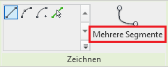
Now sketch the desired axis and exit sketch mode as usual.

See also Autodesk Help: Grids
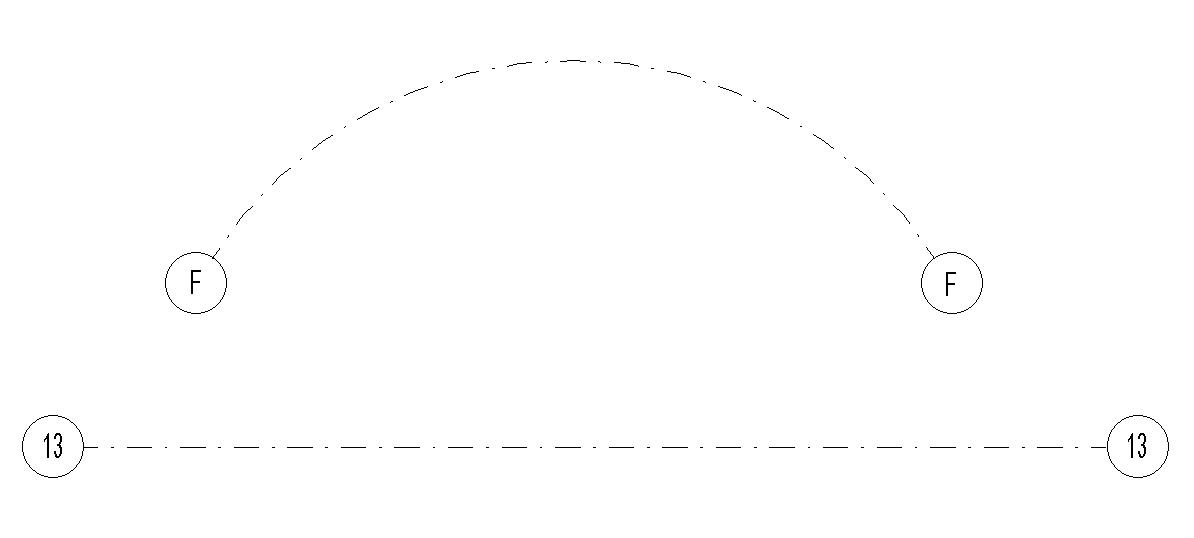
When inserting the grid, a dialog box automatically suggests a value for the axis label that increases the previous entry by a factor of 1. As a result, the character in the last position is replaced by the next character (letter or number).
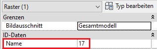
In the Properties window, you can name the axis as you like under "Name." However, it is advisable to develop a logical naming convention for subsequent steps. The most effective approach has been a system using consecutive numbers on the X-axis and consecutive letters on the Y-axis.
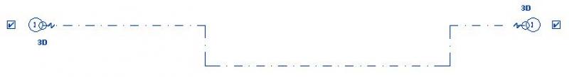
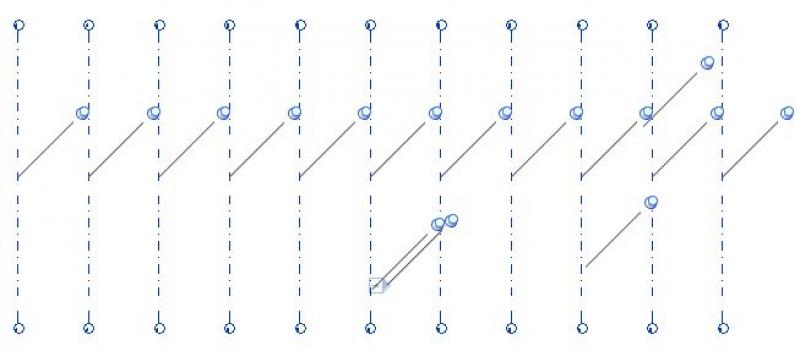
Symbols
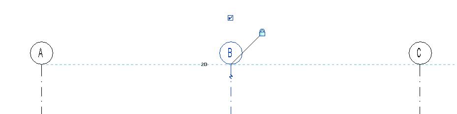
The lightning bolt icon on the grid axis is used to create a bend in the axis. This is needed, for example, at narrow points to prevent two axes from intersecting.
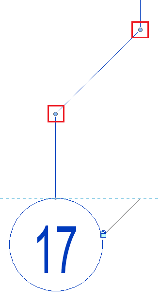
The blue dot is used to adjust the length of the grid.
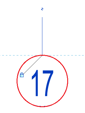
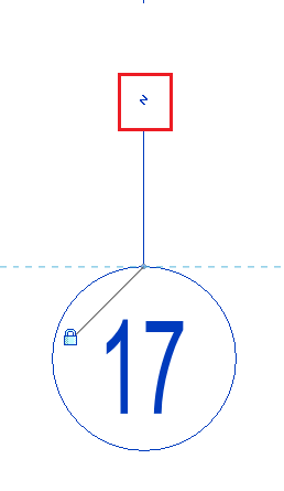
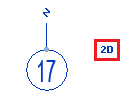
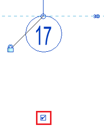
The small 3D text changes to 2D when clicked.
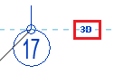
Changing the grid while 3D mode is enabled causes the entire model to shift.
In 2D mode, however, the grid changes only in the current view.
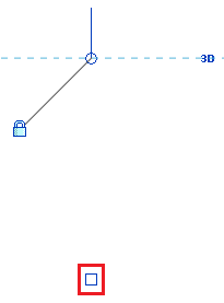
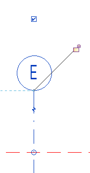
The checkbox is used to display the label circle for the grid axis.
If you uncheck the box, the circle disappears as well:
When creating additional grid axes, it is recommended that you use the "Row" command (shortcut AR).
Select the grid segment you want to arrange in a row and switch to row mode. Now enter the desired number of grid segments in the green editing bar, making sure that the "Group and align" checkbox is not selected.
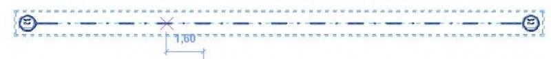

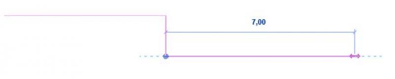
Next, move the mouse sideways in the direction you want the grid to extend, and enter the desired distance between the axes.
Press Enter to confirm the operation. The row will be created automatically.
Length adjustment
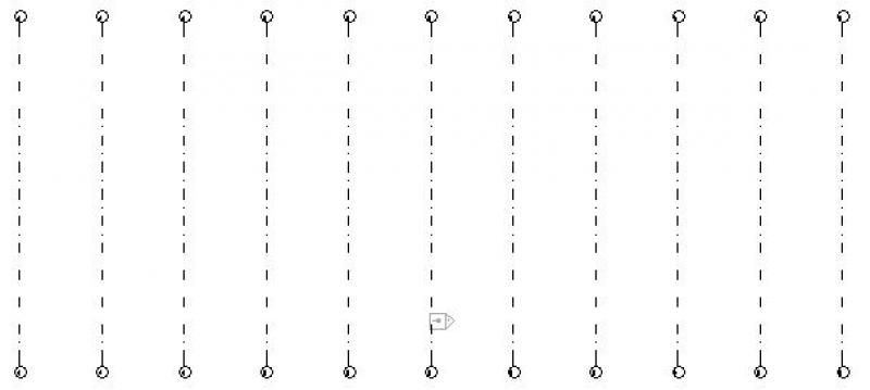
All grid lines should be adjusted:
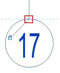
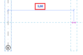
By selecting an axis, you can adjust the length of all grid lines (horizontal or vertical) in the individual views, sections, and floor plans by dragging the blue dot (below the grid label). To do this, the lock icon that appears must be closed. The guide line indicates which grid lines are being moved.
Adjusting the length of a single grid line:
If you want to adjust the length of only one grid line, select it, then click the lock icon that appears and drag the blue dot (below the grid label) to extend the grid in the desired direction.
Structural columns and beams:
Support columns and beams aligned along a grid are automatically repositioned when the grid is shifted.
Tips and Tricks
Lock grid
Once all grid lines have been created, keep the following in mind:
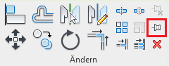
All grid lines should be locked using the pin tool. To do this, select the entire grid and click "Lock" (PN) to lock the entire grid in place. This prevents the grid lines from being accidentally moved or deleted while working on the model.
Overview
For general information on how to use the Grid Element tool, please refer to Graphisoft's basic documentation in the Help Center.
This documentation is based on the official template file 01 ARCHICAD 25 Template.tpl from the ARCHICAD 25 AUT version.
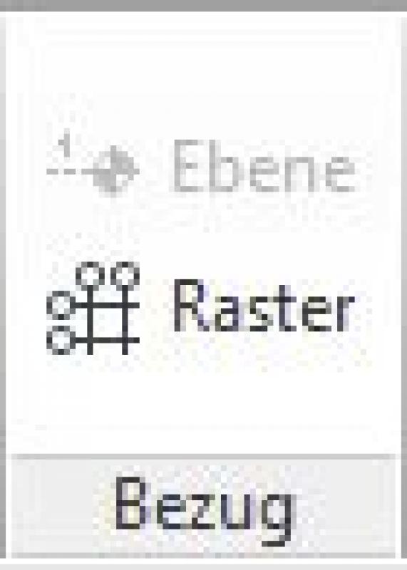
First, select the layer to be used for the grid elements: 000 Axis Grid.
The grid element is a three-dimensional element that is applied to a single floor and then automatically applies to all floors for which it has been enabled.
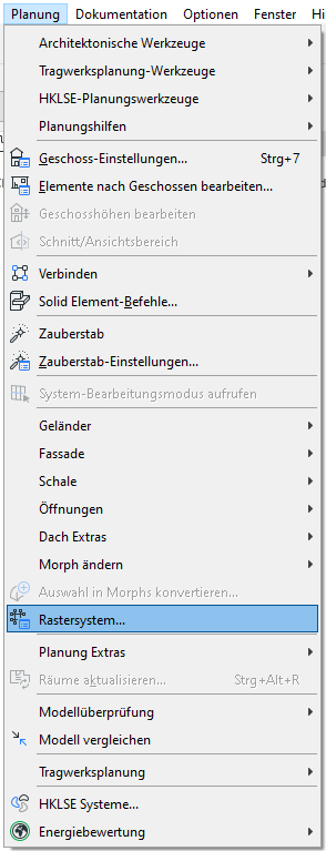
To set up a grid system, you can use the Grid Element tool; however, it is recommended that you set up the system via Planning -> Grid System to avoid, as much as possible, any rotation or misalignment that might occur when placing elements individually or manually.
Note: Once you click OK in the Grid System settings, you can no longer change the grid system. To modify individual grid elements (e.g., adjust individual spacing), use the Grid Element tool.
Default setting
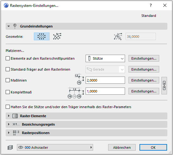
In the grid system settings, you can not only configure the grid system itself, but also specify whether columns and beams should be placed. Additionally, there is an option for automatic dimensioning.
The side settings allow you to access the default settings for the respective component or dimension. The descriptions for the individual components are explained in the articles written for that purpose.
Grid elements
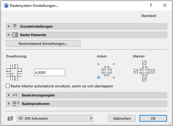
The Grid Element settings open the Grid Element tool's settings.
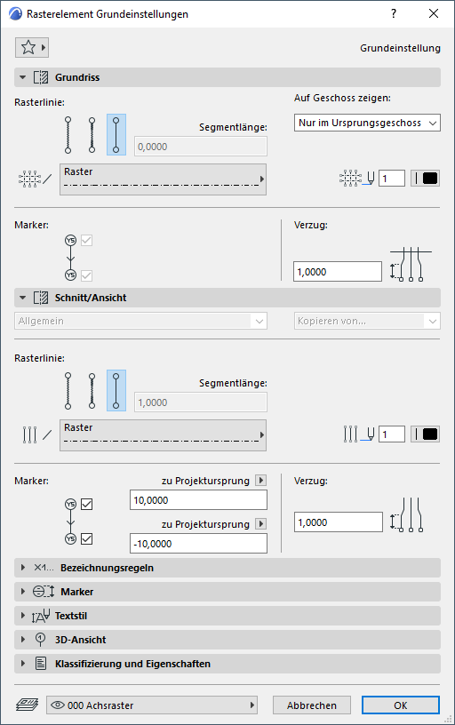
In the Floor Plan section, you can adjust the visibility of the gridlines on each floor.
Under "Section/View," you can specify the marker length as well as the amount of offset for overlaps. For both tabs, make sure to use pin 71, which is designated for the axis grid—this allows you to customize both the color and line weight of the axis grid. In the 3D View section, you can set the display style of the axis grid for perspective.
Note: In the grid settings, you can specify that grid lines should also be displayed automatically in sections/views. If section/view markers do not run orthogonally to grid elements, be sure to account for this in the section/view marker settings – to do this, the "Show non-vertical grid elements" checkbox must be selected under the "Grid" tab.
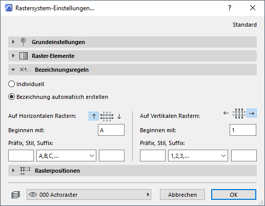
Naming Conventions
The grid elements are named here:
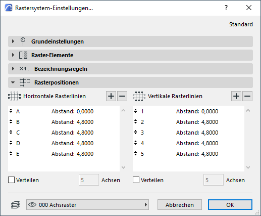
Grid positions
Grid positions are used to set the spacing between grid lines. This feature is the key difference from the basic grid tool—it ensures the system's accuracy.

Unfortunately, this content is available only to our Pro users.
If you'd like to read the full article, try the Pro account or become a Pro user.