The design of the emergency power system is based on the power requirement assessment for emergency power systems and on the currently applicable standards and technical regulations in their latest versions.
The space requirements must be adapted to accommodate the emergency power generator, including the fuel tank, distribution systems, and connecting lines, as well as any additional space required for a fuel storage room.
The emergency power room must be designed in accordance with building codes and standards on the exterior of the building, with provisions for ventilation (based on the design of the supply/exhaust air system) and for exhaust ducting.
For the system design, options include a fixed installation within the building or a container solution.
During this planning phase, the emergency power system component is positioned.
Presentation

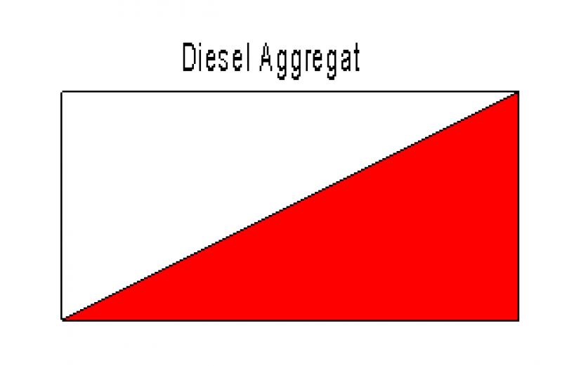
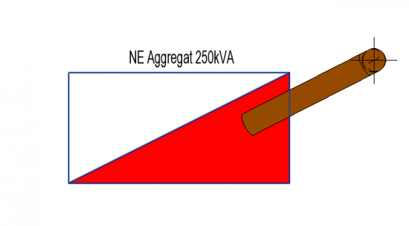
Plan view
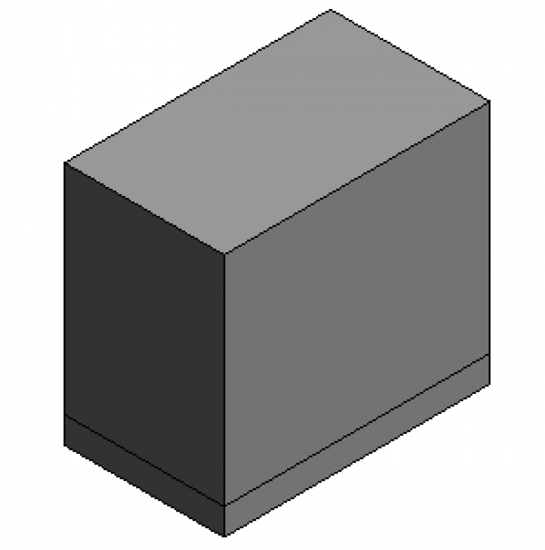
Model representation
Features
- Dimensions (space requirements)
- Maintenance area
Labeling
At this stage, the component is not yet labeled in the plan view.
Instructions
During this phase of the project, only the distribution boxes relevant to the building shell—that is, those that require their own spaces or niches—will be installed.
Note the large ventilation cross-sections required for air-cooled systems, as well as the separate tank room (1000 L or more) that is usually required. The building requirements (rooms, shafts, supply and exhaust air ducts, exhaust gas routing over the roof, etc.) must therefore be determined in consultation with the architectural team at the very beginning of the building design process.
The diesel generator for the sprinkler system is largely the same as the one used for the emergency power system.
Schematics for the distribution overview can be created in Revit.
Design and installation of emergency power systems:
The installation of an emergency power system is similar to the installation of distribution panels.
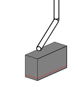
The installation of the exhaust pipe for the emergency power system is covered in a separate article.
In this phase of the project, there is no difference from the plans and models presented during the preliminary planning stage.
Features
The following characteristics are defined in this phase:
- Geometry
- Loads for TWP
- Determination of the type of emergency power system
- Reactive power
- Designation of the emergency power system
Labeling
This planning phase describes the name or designation of the device.
Instructions
The labeling of emergency power systems is based on a labeling family.
No emergency power systems need to be included in this phase of the project. The exhaust gas values, supply and exhaust air ducts, target pressure levels (LWA), and water cooling are addressed in the technical report.
Presentation
Plan view
Model representation
Features
The following characteristics must also be defined in this phase:
- Design of the emergency power system
- Type designation
- Exhaust system sizing
- Apparent power
Labeling
The following additional labeling information is required during this planning phase:
- Reactive power

Instructions

Unfortunately, this content is available only to our Pro users.
If you'd like to read the full article, try the Pro account or become a Pro user.