During this phase of the project, only distribution boxes that are relevant to the building shell will be installed—that is, those that require their own spaces or niches.
Presentation
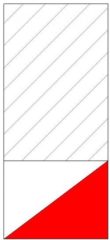
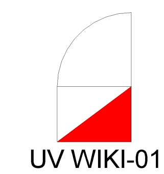
2D plan view
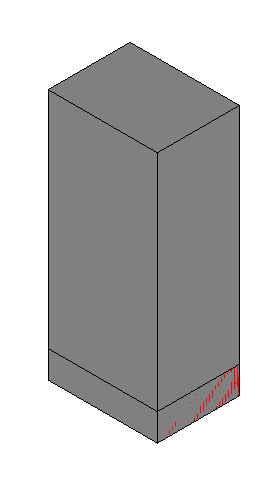
3D model visualization
Features
The following characteristics must be defined at this stage:
- Length
- Width
- Height
- Maintenance area
Labeling
At this stage, the component is not yet labeled in the plan view.
Instructions
Schemas
Schematics for the distribution overview can be created in Revit.
Creating a distribution list
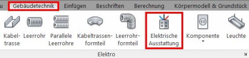
The "Building Services" tab contains a button for inserting electrical equipment. The family is placed on a single layer and can then be moved manually in the section view or by entering an offset in the Properties window.
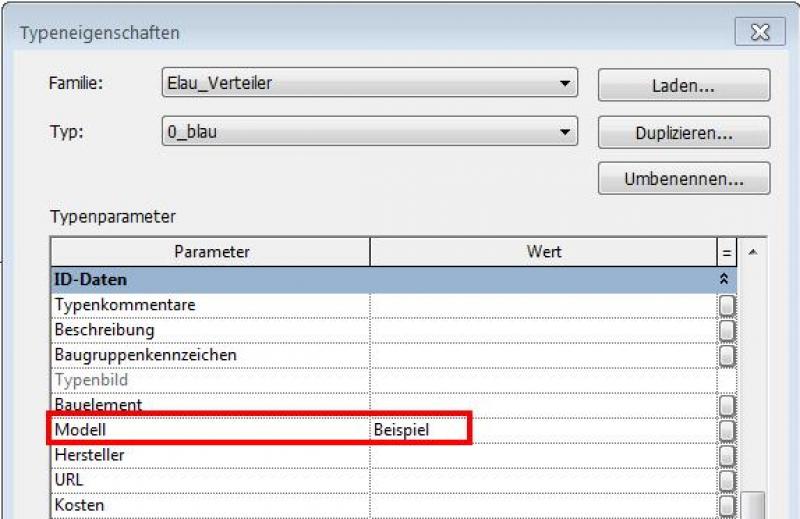
The following colors for the distributors must be defined in the type properties:
Trade: Color:
High-voltage current red
Sibel green
Fire alarm blue
IT/Telecom green
MSR red
RWA red
EMA/Alarm System green
Access control green
ELA green
Intercom green
The following colors for the distributors must be defined in the type properties:
Trade: Color:
High-voltage current red
Sibel green
Fire alarm red
IT/Telecom green
MSR blue
RWA orange
EMA/Alarm System green
Access control green
ELA green
Intercom green
All distribution panels are drawn to scale in the floor plan based on dimensional assumptions. Door openings, clearance, and maintenance space must be taken into account, and the correct types (e.g., flush-mounted, surface-mounted) must be specified. The boundaries and coverage areas of the distribution panels are shown.
The size of the distribution panel is determined based on the division units, including space, power capacity, and built-in reserve.
A distribution area is created for each sub-distribution panel. This refers to the area served by the respective distribution panel or sub-distribution panel.
Distribution panels vary in terms of their intended use, size, protection rating, power source type, supply method, etc.
Example:
- Medium-Voltage Distribution
- Low-voltage main distribution
- Meter distribution
- Sub-distribution for lighting and outlets
- Technical wall (e.g., at the fire department access point)
- IT distribution (patch panels), servers
- Measurement and control distribution
Presentation
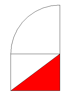
2D plan view
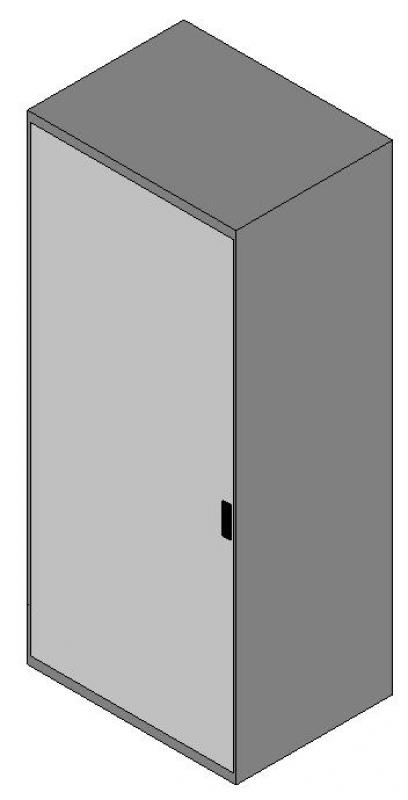
3D model visualization
Features
The following features will be added in this phase:
- Specification
- Number of doors
- Door swing
- Circuit assignment
- Type
- Connection cable
- Fuse protection
- Supply cable
- Supply cable length
Labeling
The labeling of the distribution cabinets is based on a labeling family, depending on the family type:
Instructions
The distribution boundary can be shown in the 2D plan view using a detail line.
For more information, see "Drawing Detail Lines" in Revit 2016.
The distribution area should be named in plain language based on the labeling scheme.
Presentation
The plan and model renderings are the same as those in the draft.
Features
The following features will be added in this phase:
- Type
Labeling
The labeling should be done in accordance with the design.
Instructions
The correct dimensions (based on the design changes) for each manifold must be defined. The manifold boundaries and manifold areas are drawn precisely based on the design changes. The component type is entered in the component's type properties:

Unfortunately, this content is available only to our Pro users.
If you'd like to read the full article, try the Pro account or become a Pro user.