An exhaust duct is a special type of air duct (round or rectangular) that removes combustion gases from a unit in the mechanical room to ensure proper operation. Many references therefore relate to the article on air ducts, which is recommended for further reading.
No representation in this service phase
Presentation
In this phase, the representation of exhaust ducts is the same as in the
air duct
Features
The following characteristics must be defined at this stage:
- Geometry (two-line representation by cross-section)
Labeling
In this phase, the component will not be labeled in the plan views.
Instructions
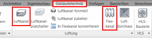
The following series of ventilation ducts can be used for this purpose:
- Rectangular duct
- Round duct
- Flexible round duct
Select exhaust pipe: Duct (rigid duct) or flexible duct (flexible pipe):
In the properties, select the pipe type (e.g., Round_T_Piece), reference plane, offset from reference plane, and system type.
Optionally, the exhaust gas volume can be entered under "Additional Flow Rate."
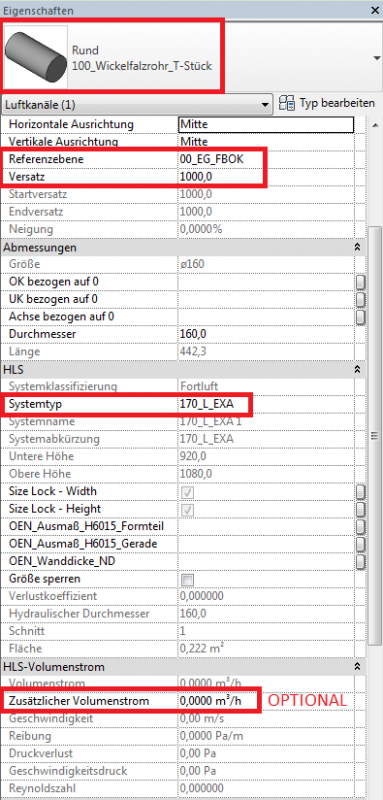
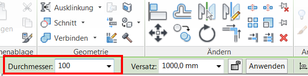
Select pipe diameter (can also be selected in Properties):
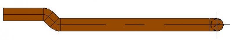
Presentation
2D plan view
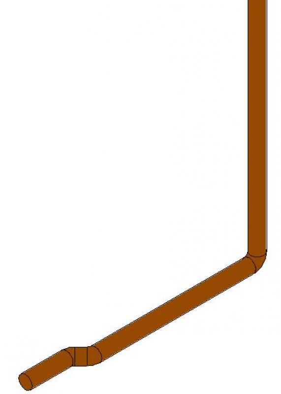
3D floor plan
Features
The following characteristics must be defined at this stage:
- Geometry based on calculations according to a device's technical specifications
- Assignment of duct designation
- Specification of air duct insulation (fire protection cladding)
Labeling
Similar to the labeling of air ducts: Labeling of air ducts during the design phase
Instructions
In this phase, follow the air duct design guidelines
At this stage, nothing has changed from the draft
Presentation
2D floor plan
3D floor plan
Features
The following characteristics must be defined at this stage:
- Angle Fitting
- Material
Labeling
Exhaust ducts must be labeled or indicated on the floor plan based on specified exhaust volumes and installation heights. Information on labeling can be found here: Labeling Air Ducts During the Design Phase
Instructions
During this phase, follow the instructions for the air duct installation

Unfortunately, this content is available only to our Pro users.
If you'd like to read the full article, try the Pro account or become a Pro user.