Trusses are open, member-based structural systems. In building construction, they are primarily used in spaces with large spans. Trusses can be designed as linear elements (truss girders) or as three-dimensional systems (spatial trusses).
Truss structures represent an interface between architecture and structural engineering and present certain challenges for users of BIM workflows. In this regard, different BIM programs vary significantly in their feature sets, meaning that modeling strategies must also be adapted to the technical capabilities available.
Search term: Skeleton construction, steel construction, wood construction, industrial building, bracing, beam, truss, truss system
At this stage, trusses are not yet fully modeled. It is recommended to create a roughly sized placeholder, such as a beam with the external dimensions of a final truss beam. See the article on beams for more information.
During this phase, trusses are modeled for the first time. In addition, the structural engineering team assesses the load-bearing capacity of the truss and, based on that assessment, assigns a material (construction material).
Presentation
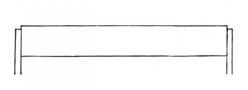
Figure 1
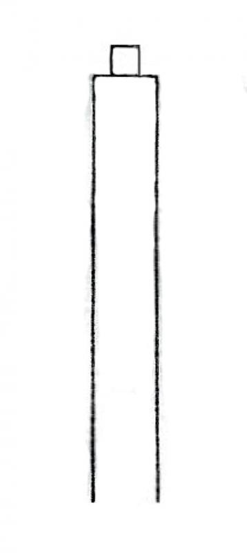
Figure 2
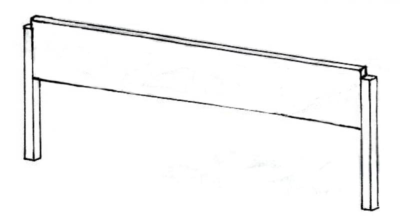
Figure 3
Features
Feature
- Status
- Supporting element
Parameters
- Width
- Gross volume
- Fire resistance class
- Element in contact with the ground
- Total surface area
- Footprint
- Height
- Tilt angle
- Length
- Lateral surface area
- Slope
- Net surface area
- Net volume
- Cross-sectional area
- U-value
- Lateral surface area
Outline Information
- External element
Labeling
In this phase, trusses are not yet labeled in plan views.
Instructions
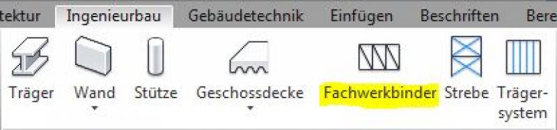
In Revit, trusses fall under the Truss category and are created using the >Civil Engineering >Truss command. Trusses are generally load-bearing components. Since they do not belong to the system families but rather to the so-called external (i.e., “loadable”) families, they must be loaded from the content as needed.
Command:
ATTENTION: Important note regarding the initial placement of trusses in the project (incorrect representation for now!)
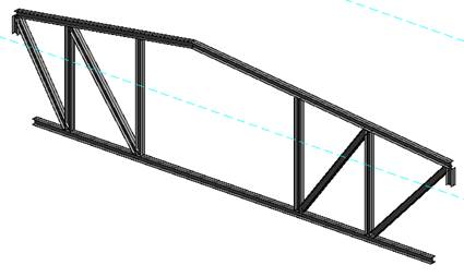
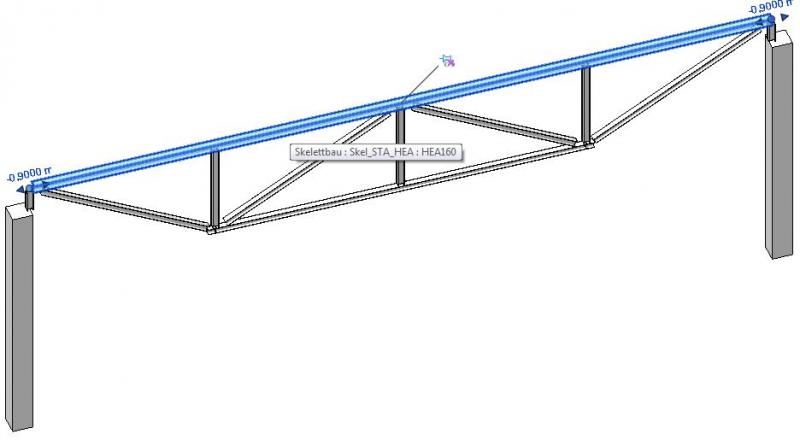
Unfortunately, trusses newly inserted into Revit are often initially displayed as "exploded," which is naturally misleading and wrongly suggests that the families aren't working (see Figure 1 below)
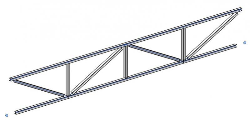
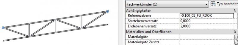
However, this is only the case until appropriate structural frame families/types are assigned as truss profiles in the project (usually steel structural profiles; see Figure 2 below).
The reason for this is that, for truss profiles that have not yet been defined, the software automatically uses the last structural family used in the project; in the case of a large reinforced concrete cross-section, the truss is displayed as "exploded."
Although it would be possible to assign suitable profiles within the family in advance, this would only lead to relatively complex and, in fact, unnecessary family nesting procedures.
Figure 1: Initial representation of a truss girder in the project with profiles that have not yet been assigned: Revit initially assigns the structural types last used in the project (in this case, reinforced concrete girders)
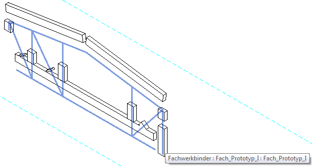
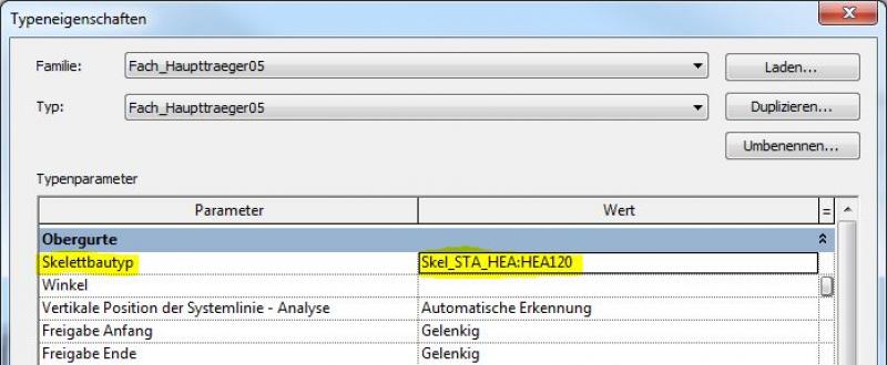
Figure 2: Illustration showing the selection of "appropriate" profiles (in this case, steel beams from the HEA profile series):
Appearance of trusses in the Family Editor (system lines only):
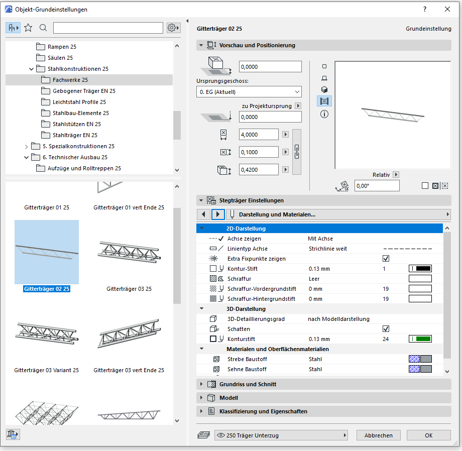
When you open a truss family in the Family Editor, you might be surprised at first because you don't see any 3D elements, just a framework of colored system lines (see the image below).
This is because the 3D elements (beams made of steel or wood structural profiles) only become visible once they are placed in the project. The family only provides a view abstracted to system lines! (A floor plan view is not provided in the family editor for trusses):
Components of trusses:
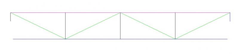
In Revit, the individual components (members) of trusses are divided into three elements based on their structural classification and are color-coded accordingly (visible when the family is open in the Editor; see last image):
- Top strap (pink)
- Lower strap (blue)
- Strips (vertical: black / diagonal: green)
Creating new components of trusses:
The general procedure for creating or modifying truss families is as follows:
- Creating members by drawing system lines: Menu > Create, Command > Web, > Web, > Web
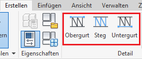
- The following applies: An upper chord is always displayed in pink, a lower chord in blue, vertical webs in black, and diagonal webs in green (this color scheme is specified by Autodesk)
- The system lines must be "tied" to the reference planes (i.e., made dependent on them using the >Align command) to ensure that the members move along with the changes in the truss dimensions! [Note from the author: This step was even overlooked by Autodesk itself in some truss families included in the content, which sometimes leads to incorrect truss representations]
Autodesk Family Content:
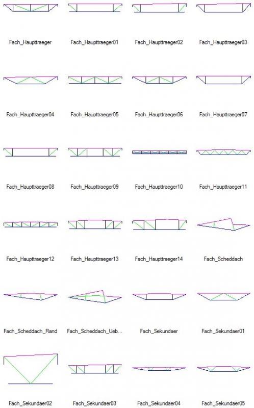
The truss families included with the Revit content are generally divided into three groups:
- Main beam
- Secondary beam
- Shed roof
Overview of Half-Timbered Truss Content:
Inserting trusses:
Trusses are inserted in the floor plan or (less commonly) in a 3D view by specifying the start and end points. Note that these points should be supported by load-bearing elements—e.g., a column or wall (see below: "Support for Trusses")
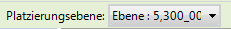
To position the truss at a specific height, you can place it on any layer in the project by selecting the >Placement Layer in the options bar:
You can also choose whether the top or bottom chord of the truss should be used as the reference height. This setting is configured in the Parameter > Support Chord (Top, Bottom) menu. The truss can be attached to existing structural planes or to planes created specifically for this purpose.
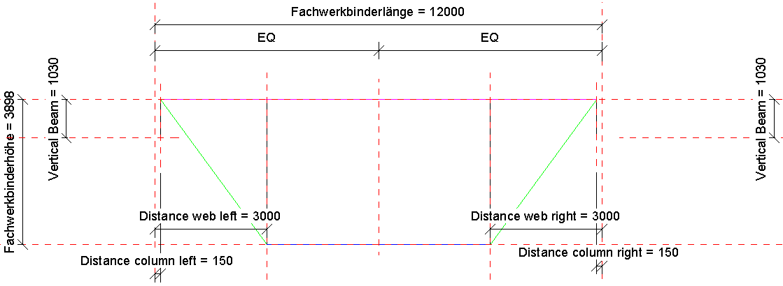
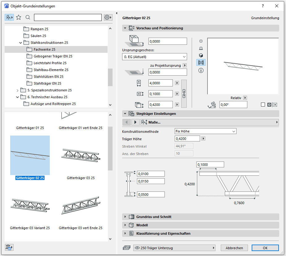
Here is an overview of the parameters that determine the truss geometry:
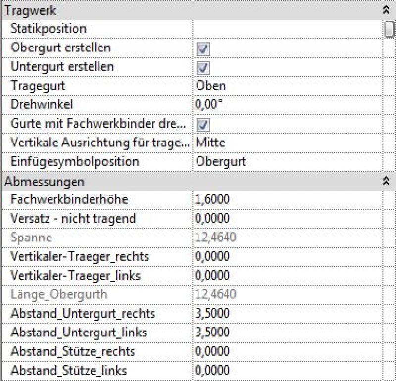
If the model is mirrored or rotated, the assignment of parameters defined as 'left' and 'right' no longer matches (relative to the origin of the truss).
Supports for trusses (start and end points):
When modeling trusses, care must be taken to ensure that the start and end points are always constrained by load-bearing elements—such as the center of a column or the axis of a load-bearing wall—to ensure that the truss makes structural sense in terms of structural analysis.
Profile mapping
The individual components of a truss (top chord, bottom chord, webs) must be assigned corresponding profiles in the project (e.g., structural steel profiles such as HEA, HEB, or similar).
This can be done in two different ways:
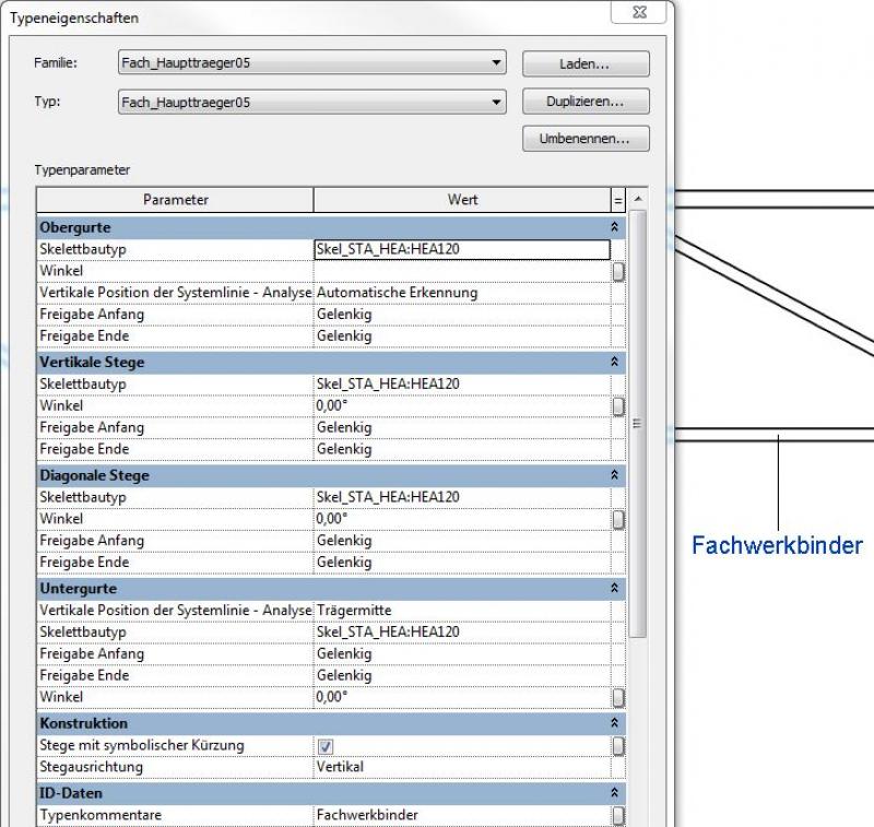
1) Using the >Edit Type command, including setting the corresponding >Skeleton Type in the type settings. However, this method allows only one uniform profile to be assigned to all webs:
Profile assignment via >Edit Type and >Skeleton Type:
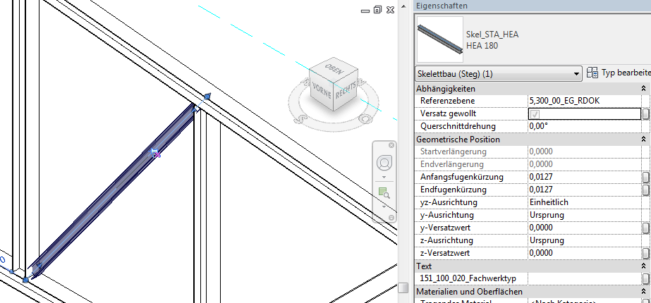
2) By selecting an individual truss member using the Tab key. This method also allows you to assign different profiles to the members! (e.g., HEA100 for a diagonal member and HEA150 for a vertical member):
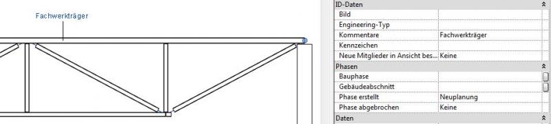
Select using the Tab key, then unlock and change the Skeleton Construction family/type via the Properties window:
If you need profiles other than the skeleton structure families already included in the project, you must load them into the project: Skeleton Structure category
Sloped trusses:
Using the >Start Plane Offset and >End Plane Offset parameters, a truss can be tilted in a manner similar to a beam, for example, to define the slope of a roof structure.
ArchiCAD offers only rudimentary capabilities for creating truss elements. While the library does contain objects that allow certain truss types to be modeled with minimal effort, these objects will fail—at the very latest—when attempting to export them to structural analysis software. If BIM-based data transfers for structural analysis are planned, it is therefore strongly recommended to work with individual elements (column and beam tools) from the very beginning.
In this phase, truss structures are supplemented with structural engineering data, and the structural design is further detailed. Secondary members of the structural system (such as purlins, rafters, struts, and similar elements) are modeled, provided that these are also to be constructed using trusses.
Presentation
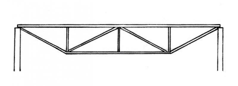
Figure 1
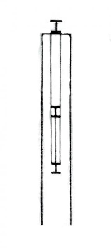
Figure 2
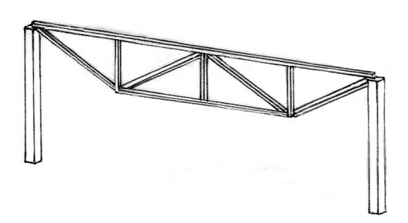
Figure 3
Features
- Ground-contacting element
- U-value
Parameters
Outline Information
Labeling
In this phase, members are labeled only in the structural design drawings:
- Load diagram: Load application
- Position plan: Position
- Architecture: Labeling of the top and bottom (beams)
Labels for trusses can be obtained from Revit Content.
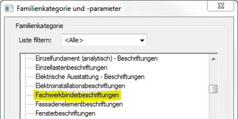
New labels can be created using the label family template >M_General Label. In the new family, the category should be changed to "Truss Tie Labels" using the >Family Category and Parameters command:
Instructions
The instructions for trusses in secondary structures correspond to the instructions under >Preliminary Planning in this article.
During this phase, as part of a defined structural design process, truss structures are further detailed and, if necessary, broken down into individual members.
Presentation
Figure 1
Figure 2
Figure 3
Features
Labeling
During this phase, structural columns are labeled by the architectural team as "ready for approval."
These include:
- Individual half-timbered components - Cross-sections (width x height)
- Truss components - Heights: Top edge, bottom edge
Ideally, labeling is performed using a family that retrieves the necessary information from the parameters and properties of the structural components:
Instance parameters:
Instructions
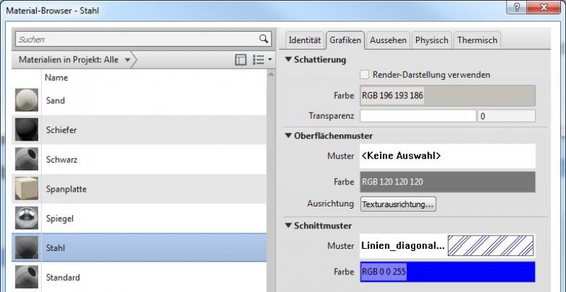
Country-specific color settings:
In Revit, the specific color schemes for submission drawings (permit drawings) are defined in the material (there is no type setting for the color fill at a coarse scale for beams): Color in the material:
During this phase, all information required for the assignment (concrete grade, etc.) is added to the members. In addition, the member is reinforced. Depending on the collaboration scenario, this can be done in 3D within the member or in 2D, independent of the model.
Presentation
Figure 1
Figure 2
Figure 3
Features
Feature
- Reference
- Undervoltage
Parameters
- Gross weight
- Net weight
Outline Information
Labeling
During this phase, the framework is fully labeled and dimensioned.
Architectural Floor Plan:
- Dimensioning of all individual truss component edges and cross-sections
- Lower and upper edges of individual truss components
Structural Design Overview:
- Dimensioning of all individual truss components and beam cross-sections
- Lower and upper edges of individual truss components
- All information relevant to the building shell
Instructions
The information regarding steel or wood construction determined during this phase must be provided by the structural engineering team and incorporated into the foundation design.
For instructions on creating new families in the "Truss Labeling" category, see the guide in this article under the section >Design >Labeling >Revit Workflow

Unfortunately, this content is available only to our Pro users.
If you'd like to read the full article, try the Pro account or become a Pro user.