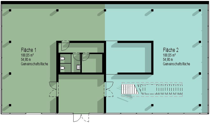
Floor plans can be used to visually represent, for example, room layouts, leasing plans, or gross and net floor areas.
By using blocks of color, their similarities or differences can be highlighted in a way that is specific to the topic.
General Information
- Plots are delineated by plot boundary lines
- Area boundary lines are created on area plans
- A separate area map type is used for each area theme (e.g., "construction phases")
- An area map type is generated from a previously created area schema
- A color scheme defines the graphical appearance
Note: Unlike room partition lines and rooms, area boundary lines and the resulting areas are view-specific. This means they are only visible in the view in which they were created.
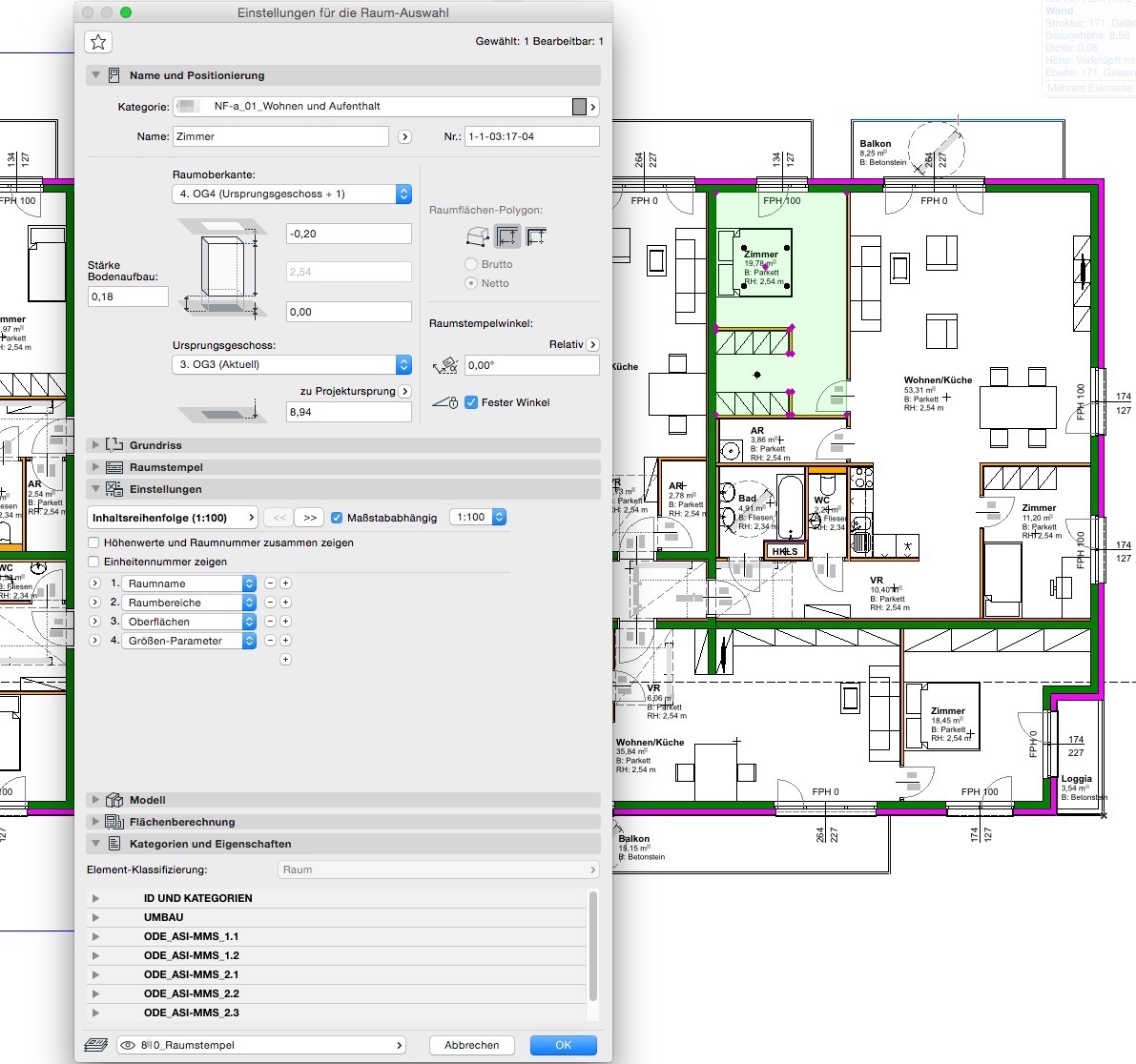
Surfaces are graphically highlighted by adjusting the room surfaces (or the parent room categories). These settings can be modified for both 2D floor plan views and 3D perspective views.
Multiple rooms can be grouped (mathematically) using the Top Stamp library element—however, this must be handled on a country-by-country basis depending on the ARCHICAD version.
The methods for highlighting and summarizing areas do not differ across the various design phases. Detailed instructions on room areas can be found under Room.
Features
Once the report is generated, the following parameters are available as a minimum:
- Area
- Perimeter
- Description
Instructions
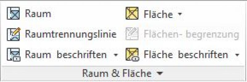
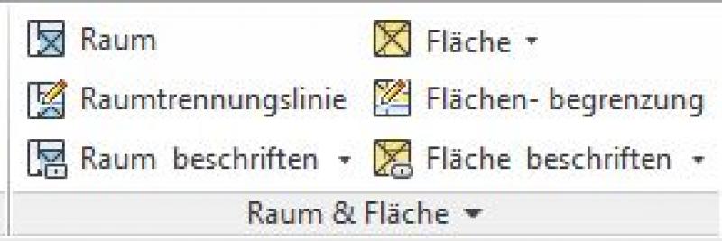
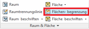
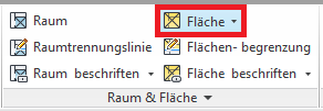
Under Architecture > Space & Area > Areas, as well as under View > Create > Top Views, you can create a floor plan.
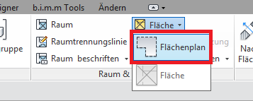
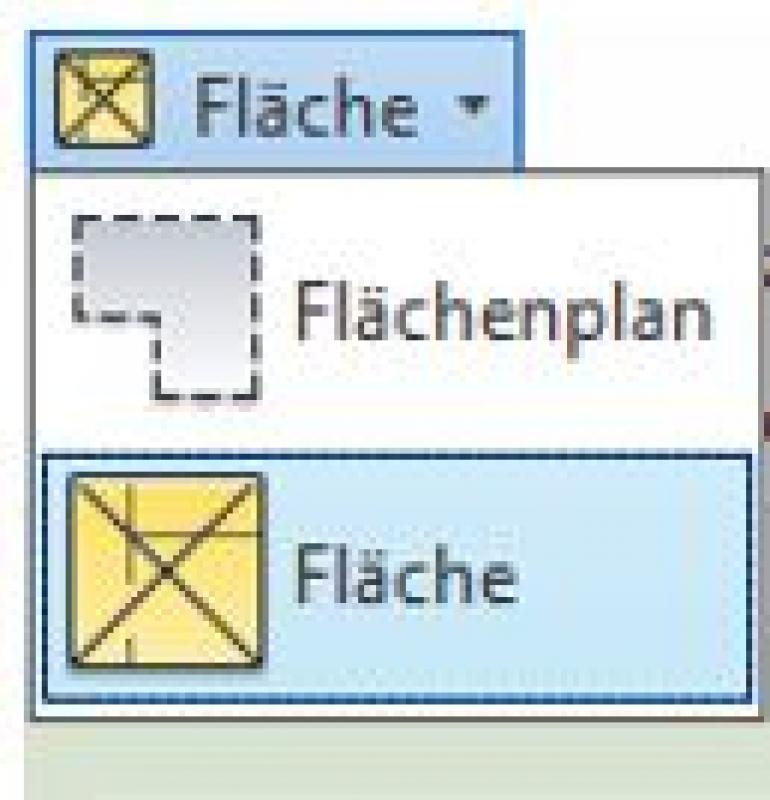
To do this, select Area -> Area Plan.
When creating a floor plan, make sure to select the correct floor plan type (e.g., construction phases, gross floor area, etc.) and the desired level (FBOK, RDUK, etc.).
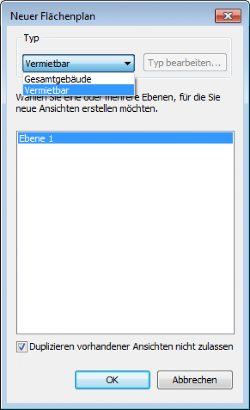
The checkbox for "Do not allow duplication of existing views" is selected by default—it is important that no views are automatically duplicated.
Clicking OK creates a new floor plan.
Note:
If the desired area type cannot be created because it does not appear in the drop-down menu, you must first create an area schema. Instructions for doing so can be found here.
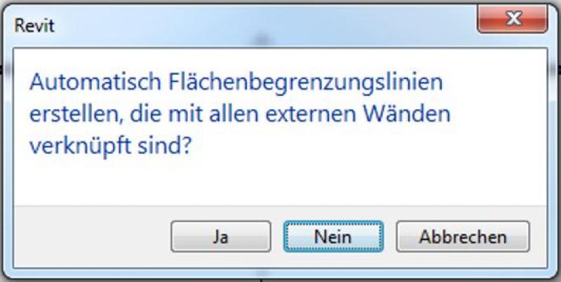
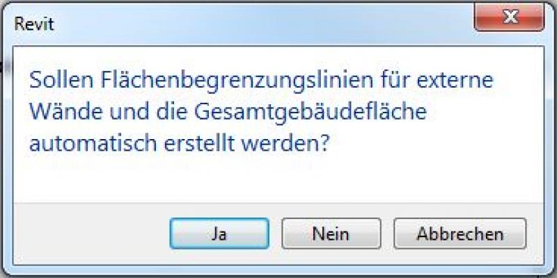
In the pop-up window that appears, click "No" to prevent the "automatic creation of area boundary lines" if you do not want this feature. Area boundary lines can be created, edited, or deleted at a later time.
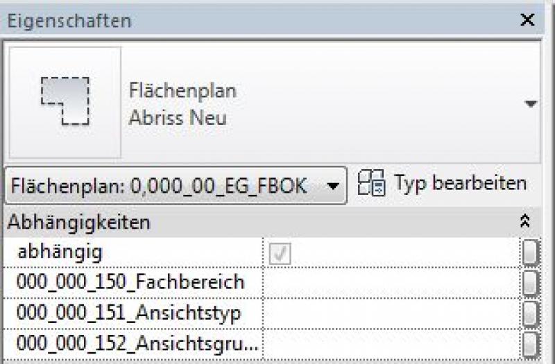
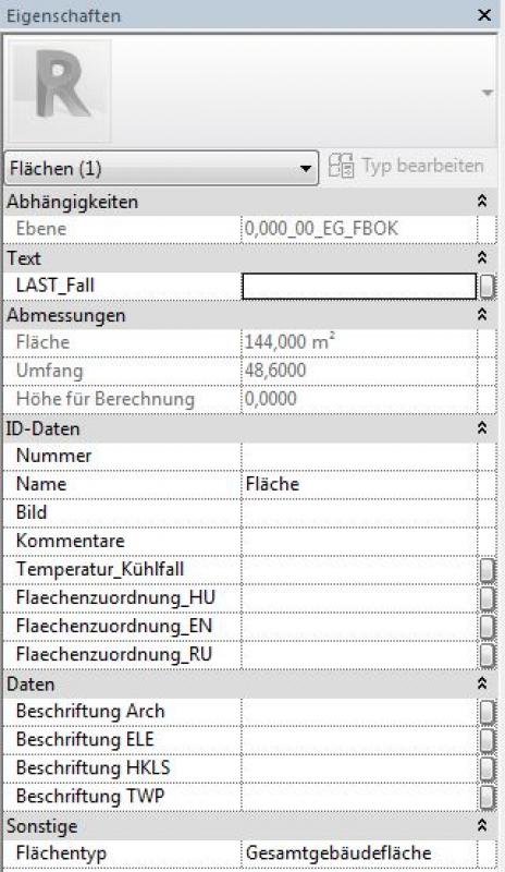
You can easily check whether the correct plan has been created in the Properties window:
Newly created floor plans have not yet been categorized and can therefore be found in the project browser under the view group ???-> ??? -> ???.
Labeling
Just as with rooms, you can also create labels for areas that retrieve parameters from the area.
Instructions
Creating a new area plan type/area scheme:
Select the gray "Space & Area" section:
Select the "Area and Volume Calculations" option:
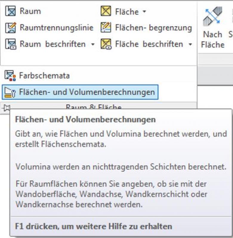
This opens the "Area and Volume Calculations" window:
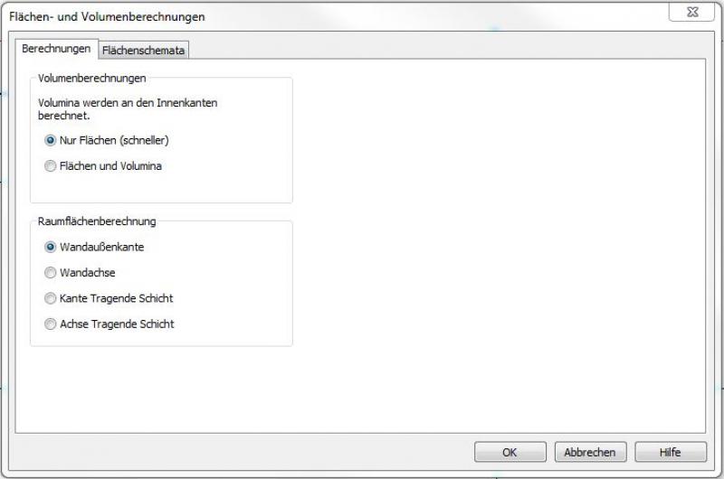
Here, you can create new area layouts, which are then used to generate the area plan type. This type can later be selected as a "template" when creating new area plans.
In the "Area Schemas" tab, click the "New" button to create a new schema and give it a meaningful name.
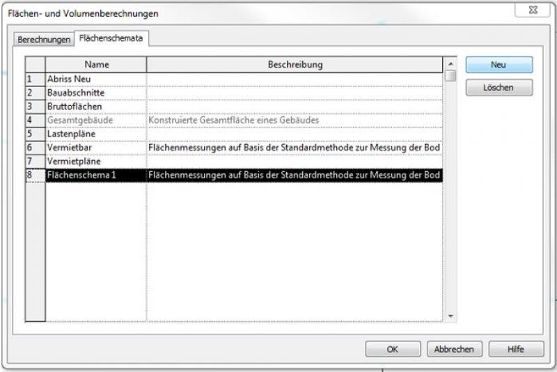
It is important to choose meaningful names if multiple area plans with similar names are to be created as planning progresses. This allows the plan types or area schemes to be distinguished from one another.
A detailed description of the rules can be found here:
See Autodesk Help: Face Type and Face Type Rules
Net floor area
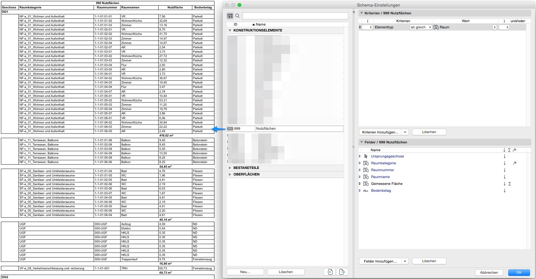
For analyzing room areas, a default list is available under Reports > Elements > 000 Room Book; this list can be customized by the user.
The analysis of room areas can be easily controlled using room categories. Subsequently, the ID, room number, and room name are all well-suited for logically grouping different rooms:
Gross floor area
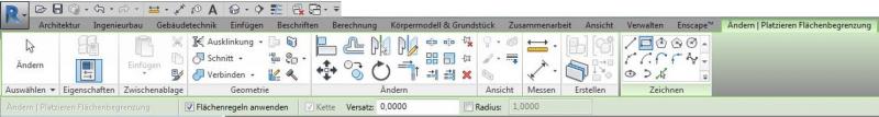
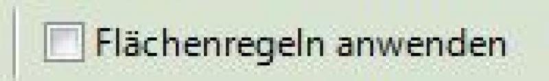
To calculate the gross floor area, a new floor plan is created using the "Entire Building" floor plan type. Make sure that the "Automatically create area boundary lines" option is enabled. With this function, Revit detects the building’s exterior walls and automatically places the necessary area boundary lines to generate the area.
When you select this area, you can check the dimensions in the Properties pane:
Note: With complex building shapes, errors may occur during automatic detection. Manual correction is then essential.
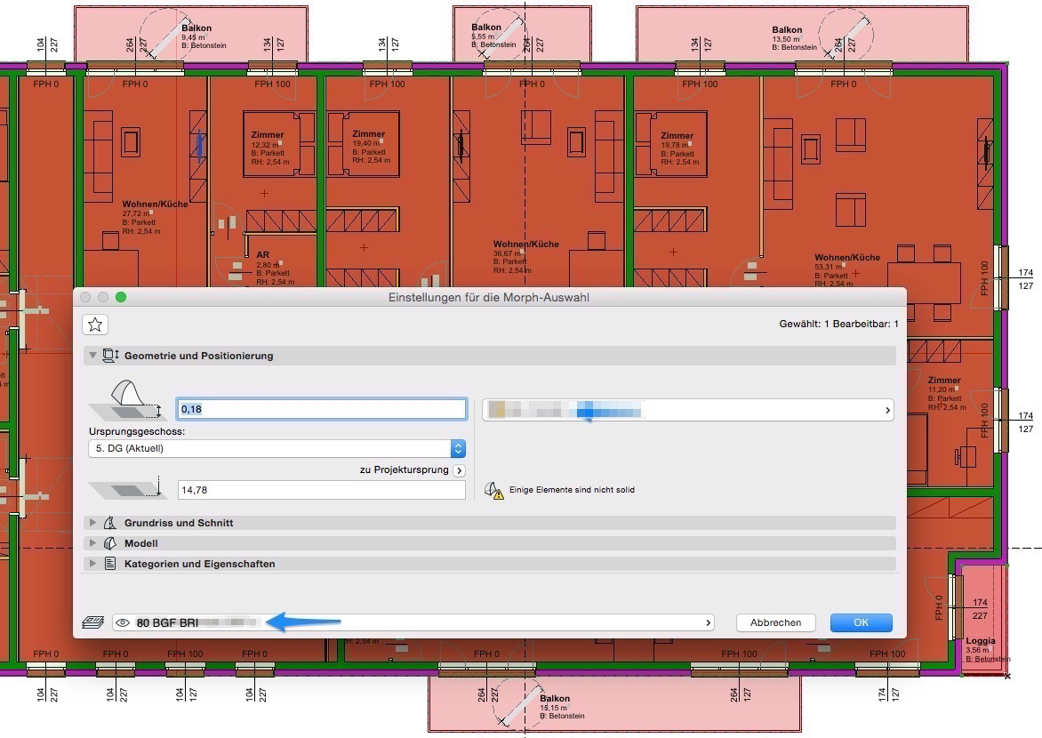
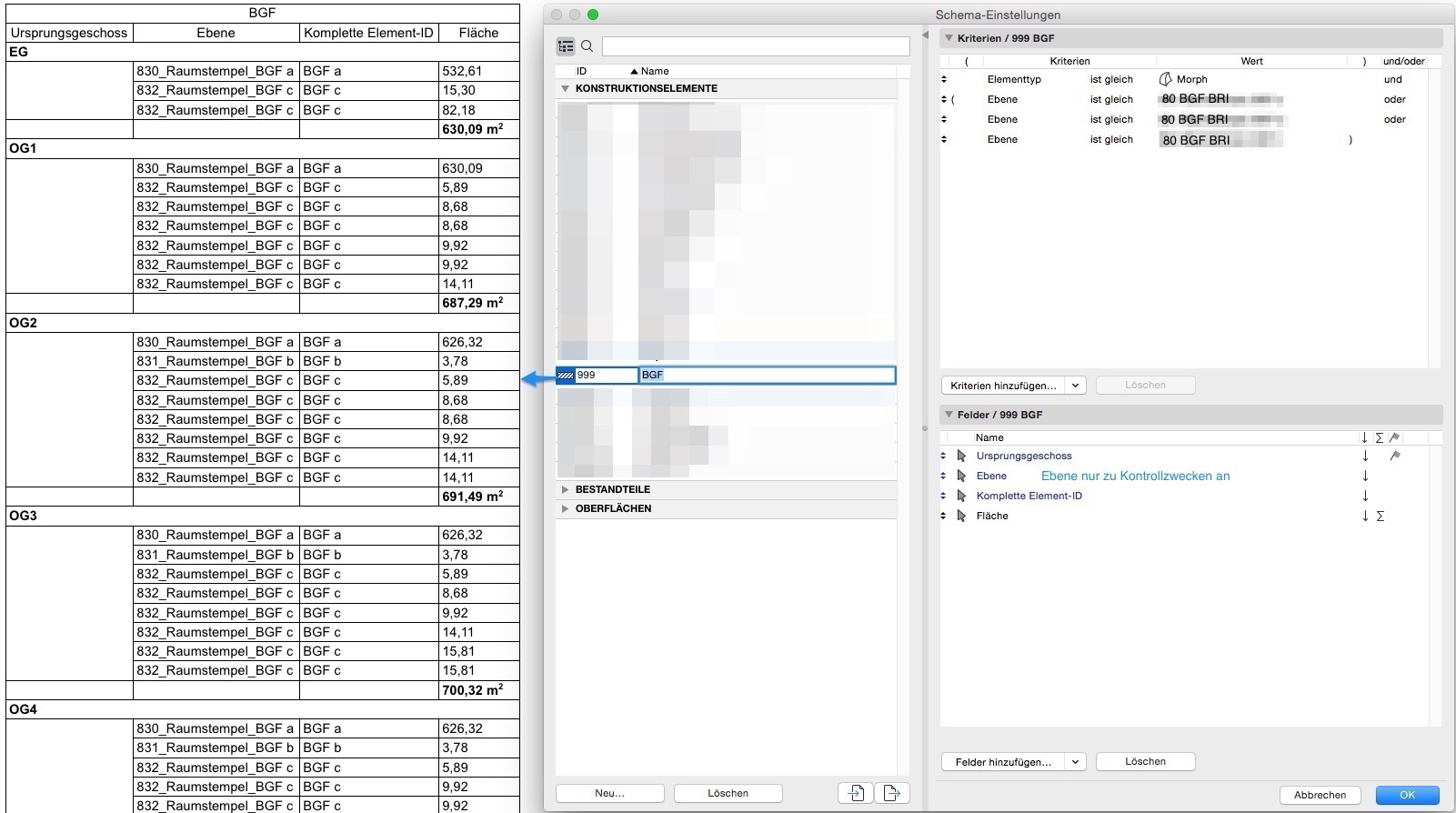
Hatching or morphs can be used to determine and evaluate the gross floor area (GFA). To be exported in an IFC file, the areas should be created as morphs. These can be evaluated in the same way as hatching.
The GFA can be created as a morph surface or as a morph solid. Both can be used to determine the GFA; the solid can also provide the BRI—however, the BRI can also be determined using the morph base area and floor height.
Exceptions
Independently defined areas
These are not associated with building components and are not linked to external walls during creation.
To do this, prevent the automatic creation of area boundary lines in the pop-up window during creation by clicking "No":

Use the area selection tool to define the desired areas.
Define the boundaries of the shapes using the drawing tools.
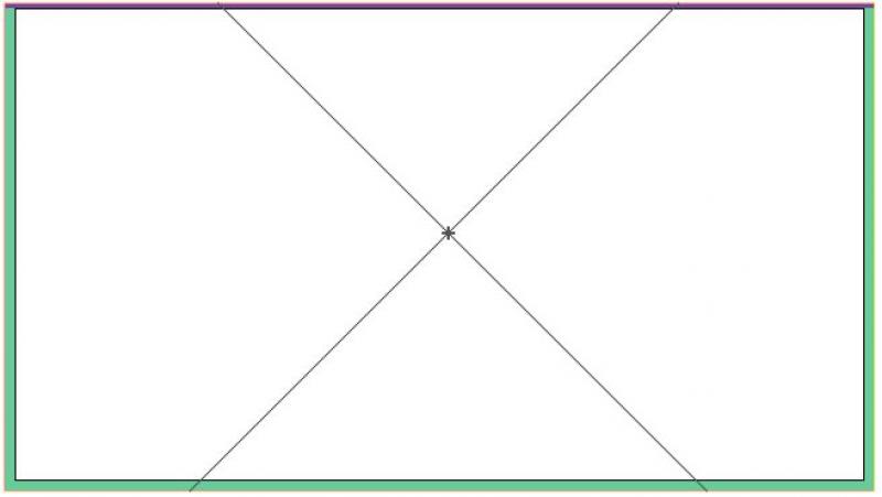
Then use the "Area" command to place the area(s).
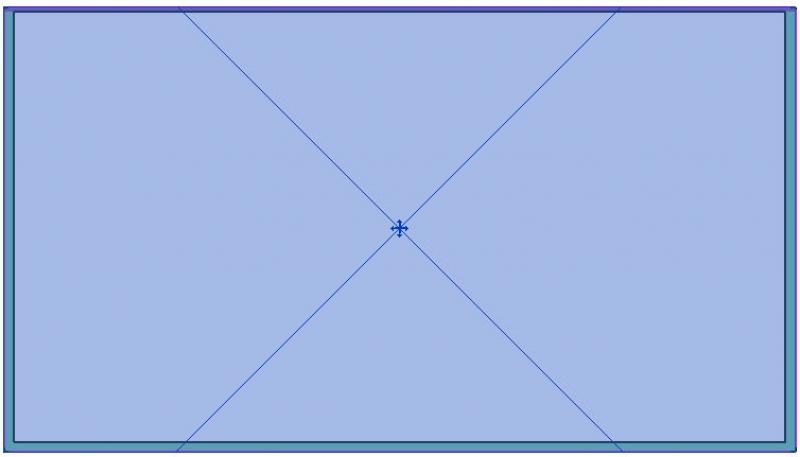
If the area has been successfully placed, this is indicated by an "X" in the selected area.
Rooms are generally created in association with the building elements surrounding them. If a room is not enclosed—or not fully enclosed—by building elements, a line can be used instead with the "Room Boundary" function.
Manual, i.e., unlinked, placement is still possible (room boundaries in the building elements or room separation lines must be deactivated)—in this case, however, the room will no longer be automatically updated on command, and errors may occur in the area calculation.
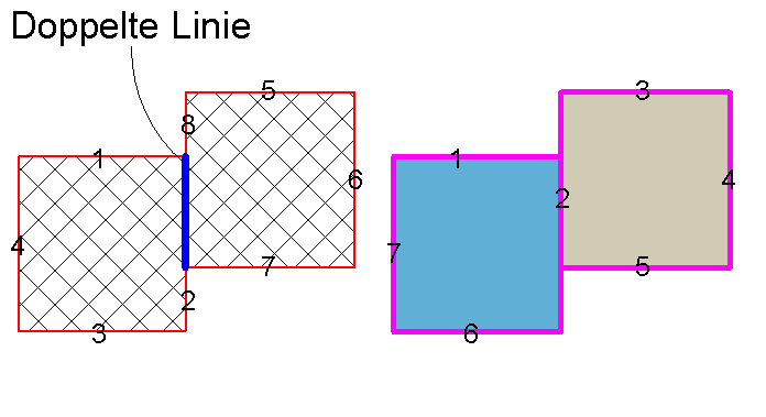
Unlike hatching, you do not need to draw boundary lines twice when working with areas.
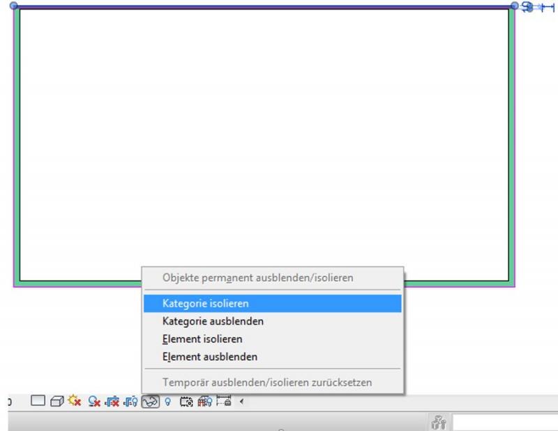
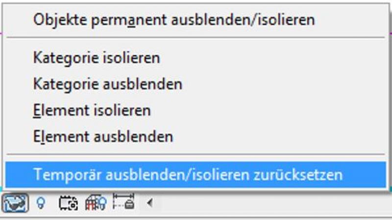
You can undo this hiding using the HR shortcut or by clicking the familiar icon again:

Unfortunately, this content is available only to our Pro users.
If you'd like to read the full article, try the Pro account or become a Pro user.