Cable trays (also known as cable troughs) are used to route cable bundles (primarily horizontally) within buildings. There are also so-called riser trays, which run vertically. Unlike conduit, cable trays are designed to allow access to the cables they contain at any time. Cable trays therefore require a certain amount of clearance above them to allow for manual access.
Cable support systems include:
- Cable tray
- Mesh cable trays
- Cable ladders
- Parapet channels
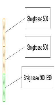
- Riser
- Piping is not covered in this article
This component is not yet shown in this planning phase.
Presentation
If a graphic representation is requested at this stage, the component is considered
Features
The following characteristics are defined in this phase:
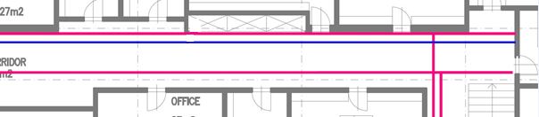
- Geometry of the main routes (two-line diagram)
- Type of element
Labeling
During this phase, the component is labeled according to the type of routing used.
Ideally, the elements are labeled using a family that retrieves the necessary information from the parameters and attributes of the routings.
Instructions
Construction of a cable tray
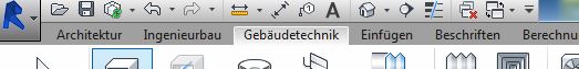
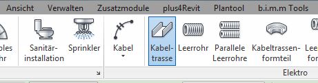
The "Building Services" tab contains the button for creating a cable route. The main routes are placed on the floor plan.
The "Cable Trough" component is a family of components.
The routing components are configured in the cable route properties.
Graphical modifications are only possible to a limited extent and are made through the font editing feature.
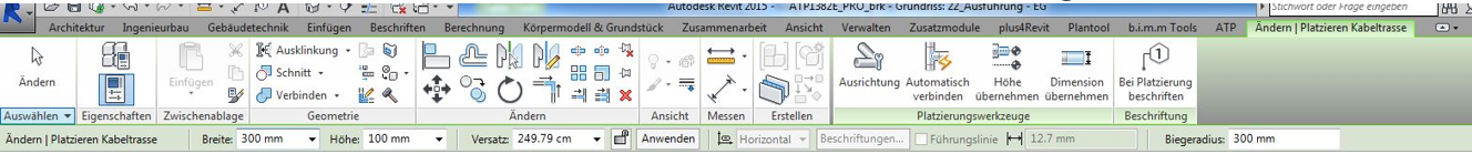
The cable route type is created based on the installation method using the Building Services > Cable Route toolbar:
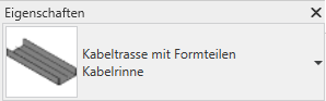
Select the desired installation type from the Properties drop-down menu. If the required type is not available, create a new one (under Edit Type > Duplicate).
The cable routes are modeled in 3D, to scale, and at their actual height. These settings are configured in the Edit/Place Cable Route menu.

During this phase, the cable routes are defined in greater detail and categorized by type (assigned by trade).
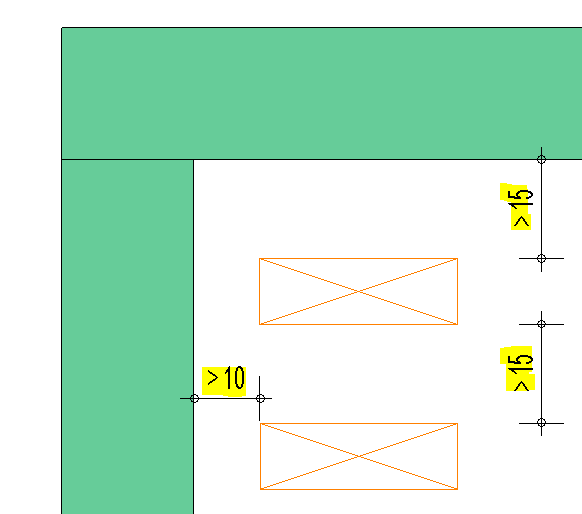
When modeling cable trays on top of one another, a clearance of 15–25 cm between them and from other structural components should be maintained.
For cable runs mounted on walls, a clearance of at least 10 cm from the wall should be maintained.
Presentation
2D floor plan
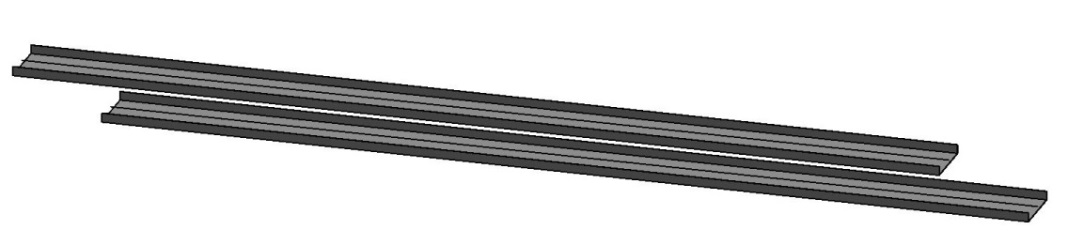
3D model visualization
img 36
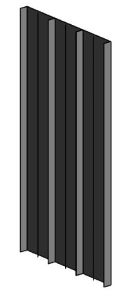
img 38
Features
The following characteristics are defined in this phase:
- Width
- Height
- Installation height
- Mounting according to fire resistance class
- Configuration according to functional integrity
- "Separating bar" design
Labeling
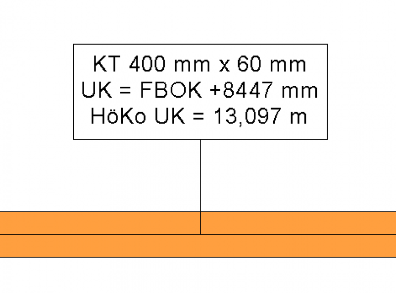
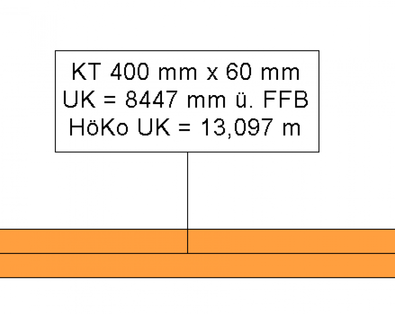
The labeling is done using the following label family:
| Name Label Family | Example Label |
| BS_Katr_TypeName_Dimensions_UK_FBOK_AT | GTR_E0 300 mm x 100 mm |
The labeling is done using the following label family
| Name Label Family | Example Label |
| BS_Katr_TypeName_Dimensions_UK_FBOK_DE | GTR_E0 300 mm x 100 mm |
Instructions
During this phase of the project, all cable routes must be coordinated with HVAC and electrical installations, and any cable conflicts must be resolved as necessary.
For more information, see the Construction Specifications Process Standard.
You can avoid conflicts by using the Collision Check tool. For more information, see the instructions under Collision Analysis.
Cable routes are not shown in this phase of the project.
In this phase of the project, the cable routes are created in the model with their correct dimensions and elevations.
If cable runs cross a fire compartment or a support, they should be interrupted.
Optional: Detail showing the clearance before and after the wall, as specified in the approval.
In order to prepare a bill of quantities, it is necessary to define all cable routes shown in the model during the construction design phase by type, purpose, and dimensions.
Presentation
The plan and model renderings correspond to the phase as shown in the draft.
Features
The following characteristics are defined in this phase:
- Installation height
Labeling
- BS_Kata_Dimensions_UK_FBOK_00_AT
- BS_Kata_Dimensions_UK_FBOK_00_EN
Instructions

Unfortunately, this content is available only to our Pro users.
If you'd like to read the full article, try the Pro account or become a Pro user.