Escalators are a special type of staircase. Because they are electrically powered, they require electrical design considerations and must be provided with relevant specifications, such as electrical connection ratings.
In general, the same design and content requirements apply to escalators as to stairs: General.
Modeling is not yet necessary at this stage.
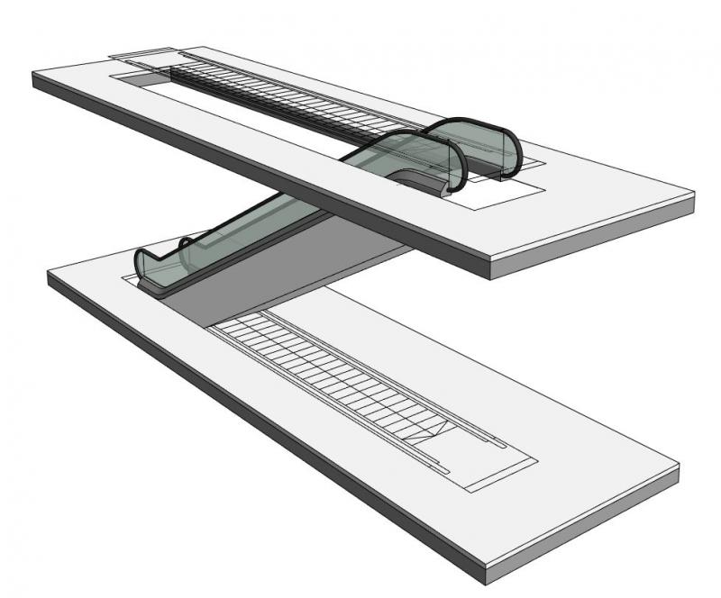
In this phase, escalators and moving walkways are modeled for the first time.
Presentation
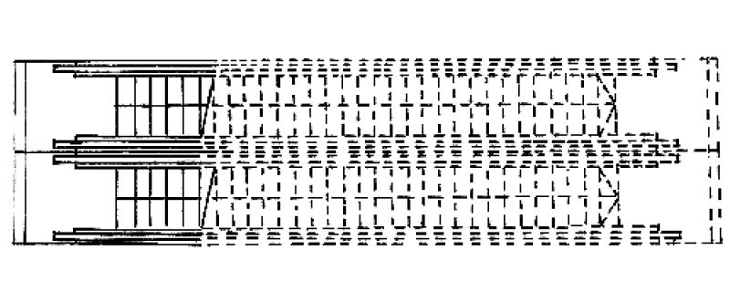
Figure 1
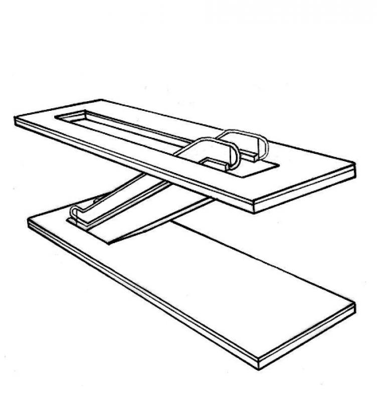
Figure 2
Features
Feature
- Number of performances
- Number of podium finishes
- Number of inclines
- Accessible
- Fire resistance class
- Emergency exit
- Reference
Parameters
- Wide stance
- Overall height
- Height of inclines
Outline Information
Labeling
At this stage, it is not yet necessary to label the component.
Instructions
Separate families are required for escalators and moving walkways. The model designation should indicate the angle of inclination and the lift height for each model.
Examples:
- The 30° model with a head height of 5.40 meters produces an escalator with a 30-degree incline and a head height of 5.40 meters.
- The 12° incline, 5.40-meter-high moving walkway model produces a moving walkway with a 12-degree incline and a vertical rise of 5.40 meters.
Once the family has been loaded, you should first review the existing types and, if necessary, duplicate and modify them. Any new types added should follow a consistent naming convention.
Any necessary openings in the ceiling are either cut out of the ceiling using the "Edit Boundary" command or modeled as a cut-through.
Overview
The basic modeling of escalators in ARCHICAD does not differ significantly across the various design phases; however, the amount of information (alphanumeric and detailed, as required or specified by the manufacturer) increases with each design phase.
An escalator, defined as an object spanning one or more floors, is placed using the object libraries.
For general information on how to use the "Escalator" library element, please refer to the basic documentation provided by Graphisoft in the Help Center.
This documentation is based on the official template file 01 ARCHICAD 20 Template.tpl from the ARCHICAD 20 AUT version.
Building components classified as service ducts are those necessary for providing access to a building—they are thus defined as access components.
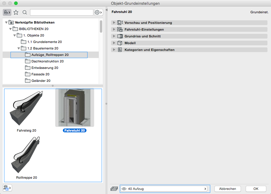
First, select the floor to be used for the escalator 40 elevator:
Preview and Positioning
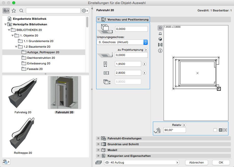
On this tab, you must specify the location relative to the ground floor, the dimensions, and the total height of the hoist.
Note: If a single escalator spans multiple floors, the floor with ground-level access should be selected as the starting floor.
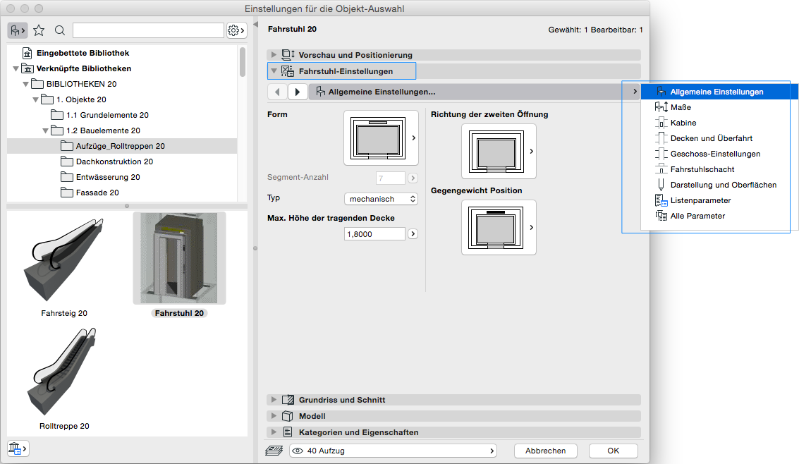
Settings
In the escalator settings (the same applies to elevators and moving walkways), the first step is to configure the individual settings regarding dimensions:
The following settings define the floor-specific display, similar to the settings for the staircase.
Floor plan and cross-section
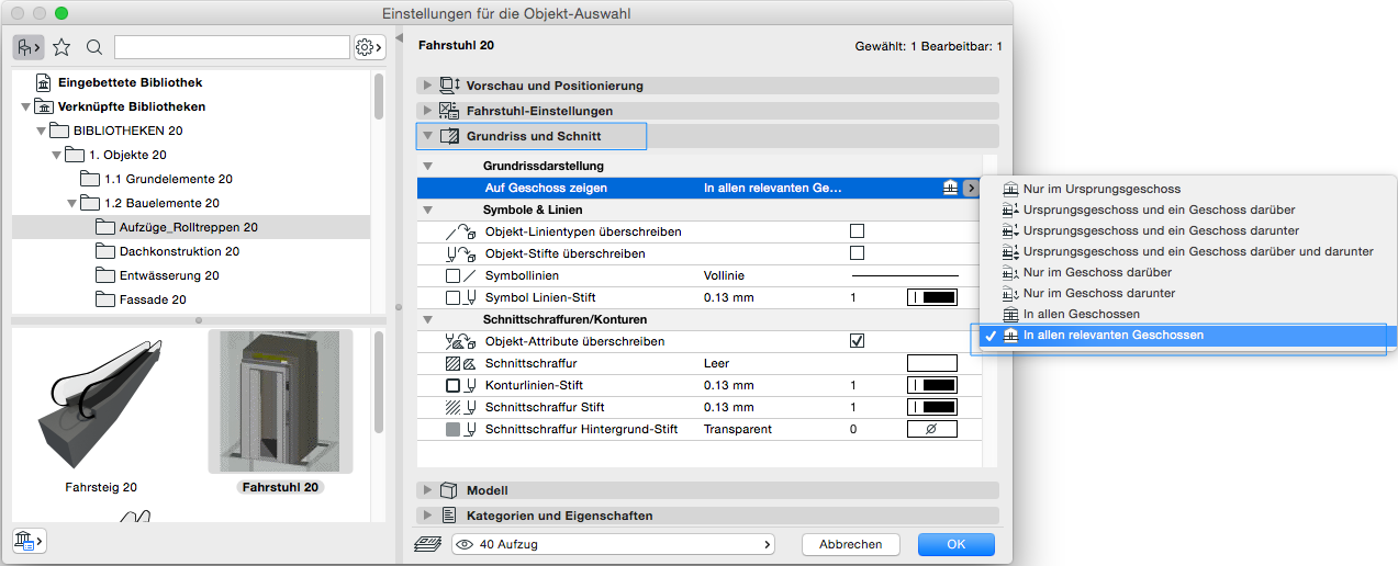
For floor-specific display, you must specify here on which floors the escalator should be shown—as with a normal staircase, the option applies to the starting floor and the floor above it.
Categories and Features
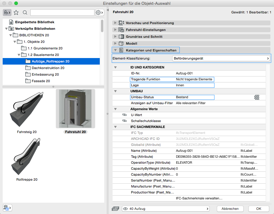
Element classification is the first definition in the Categories and Properties section—see also Classification. When you select the "Transport Equipment" classification, only those attributes available for this classification according to IFC attributes are displayed in the lower field area.
The three properties that also serve additional functions within ARCHICAD are Load-bearing, Location, and Renovation Status—these affect either the structural representation method, the envelope function (in other programs), or the renovation filter. All other attributes must be selected individually or determined in accordance with the project’s organizational guidelines (e.g., project manual or organizational manual).
During this phase of planning, alphanumeric information is added to the component.
Presentation
Figure 1
Figure 2
Features
Parameters
- Performance
Outline Information
Labeling
At this stage, it is not yet necessary to label the component.
Instructions
In this phase, you must add the features to the part by entering the corresponding parameters.
During this phase of planning, additional alphanumeric information that is relevant under building codes is added to the building component.
Presentation
Figure 1
Figure 2
Features
Labeling
For this phase, the escalator should be labeled in the same way as a regular staircase.
Instructions
The characteristics to be added during this phase must be defined on the component.
During this phase, all relevant information regarding the request for proposals is added to the component.
Presentation
Figure 1
Figure 2
Features
Feature
- Number of performances
- Number of inclines
- Step on the running line
- Hollow stair spindle
- Solid stair spindle
- Center-stringer staircase
- Minimum thickness of the stair tread
- Minimum tread depth on the inside
- Status
- Double-stringer staircase
Parameters
- Step on the tread
- Gross volume of the stair run
- Height of inclines
- Length of stair run
- Net volume of stair run
- Overhang
Outline Information
Labeling
During this phase, the lift height, the clearance below, and the clearance above are marked.
Instructions
The relevant parameters are typically entered by the experts in the field, who are usually part of the architecture or AVA department.
Note 1:
Revit is not yet capable of rendering 3D escalators or moving walkways in the standard plan view format used in the DACH region. A workaround is therefore required.
This primarily applies to floor plan views (horizontal sections).
Note 2:
In 3D views and perspectives, 2D symbols are usually distracting. The appearance can be significantly improved by turning off the 2D symbols using the Overrides Visibility/Graphics command in the General Model category. If this occurs frequently, it is generally preferable to control this via view templates.
The basic process for modeling an escalator in ARCHICAD remains the same throughout the various design phases.
The new features and parameters added for this phase must be entered in the appropriate fields of the component's settings dialog.
The description of the settings dialog and the corresponding procedure can be found in an earlier section of this article.
The labeling and dimensioning of components should always be done associatively. Instructions on how to do this in ARCHICAD can be found in the relevant articles.

Unfortunately, this content is available only to our Pro users.
If you'd like to read the full article, try the Pro account or become a Pro user.