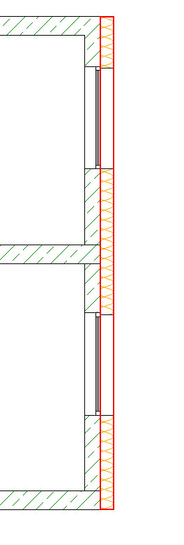
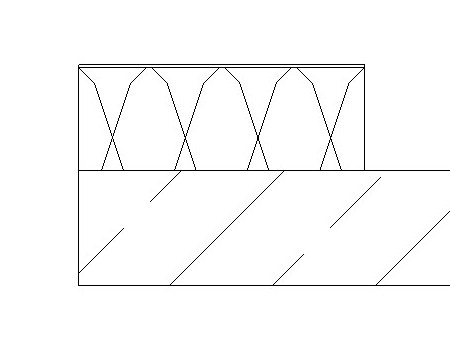
An external thermal insulation composite system (ETICS) is used for exterior facade insulation and essentially consists of two components. The first is the insulation core, which is typically bonded to the building shell using adhesive mortar and, if necessary, additionally secured with anchors. The other is the plaster layer, consisting of reinforcement plaster, reinforcement mesh, and finish plaster.
The modeling method for external thermal insulation composite systems is based on the general strategy for handling multi-layer components. In most cases, however, ETICS facades are modeled as multi-layer components separate from the bare wall starting at a certain stage, as this simplifies analysis, construction scheduling, and labeling. (This is referred to as hybrid modeling.)
External thermal insulation composite systems (ETICS) are created in Revit using walls.
These walls are classified as partition walls and may therefore consist of multiple layers. If necessary, they can also extend over several floors.
Not required yet
In this phase, ETICS facades rarely appear as separate elements. In the spirit of phase-appropriate modeling, they are still part of an overall wall assembly at this stage. This reduces the modeling effort and facilitates changes as well as variant analyses. Of interest in this context are the articles Phase-Appropriate Modelingand Multi-Layer Construction.
Not required yet
Even at this stage, ETICS facades rarely appear as separate elements. In the spirit of phase-appropriate modeling, they are still part of an overall wall assembly at this stage. This reduces the modeling effort and facilitates changes as well as variant analyses. Of interest in this context are the articles Phase-Appropriate Modelingand Multi-Layer Construction.
The component is created at this stage at the latest.
Graphical representation:
Features
In this phase, the object is created. The required characteristics are determined by the object's modeling and material definition.
The following characteristics should be defined at this stage:
- General: Type designation, Type marking, Part code (Type comment)
- Generating: Length, Width, Height
- Calculated: Area, Volume
- Simulation: Location of the building element, base plane
- Architecture: Location of the building element, component reference, floor
- Material: Material type, Material grade
Labeling
At this stage, it is not yet necessary to label the component.
Instructions
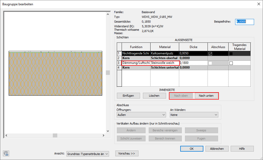
The template already contains an ETICS type. If modifications are needed, you must first duplicate the existing type. As usual, you can then make the changes in the duplicate, which has been renamed accordingly. When modifying the type, it is recommended that you enable the preview.
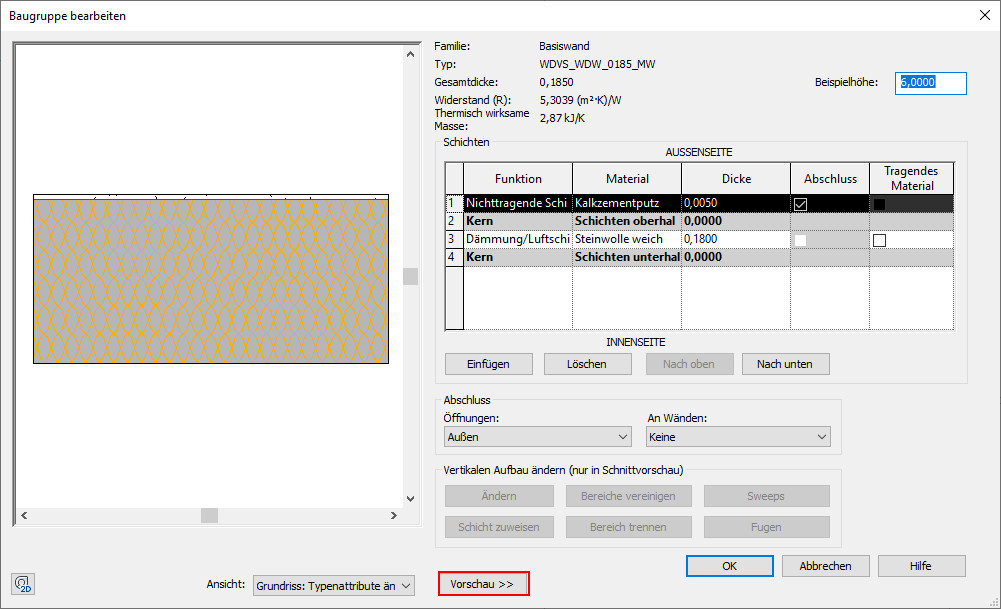
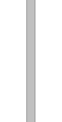
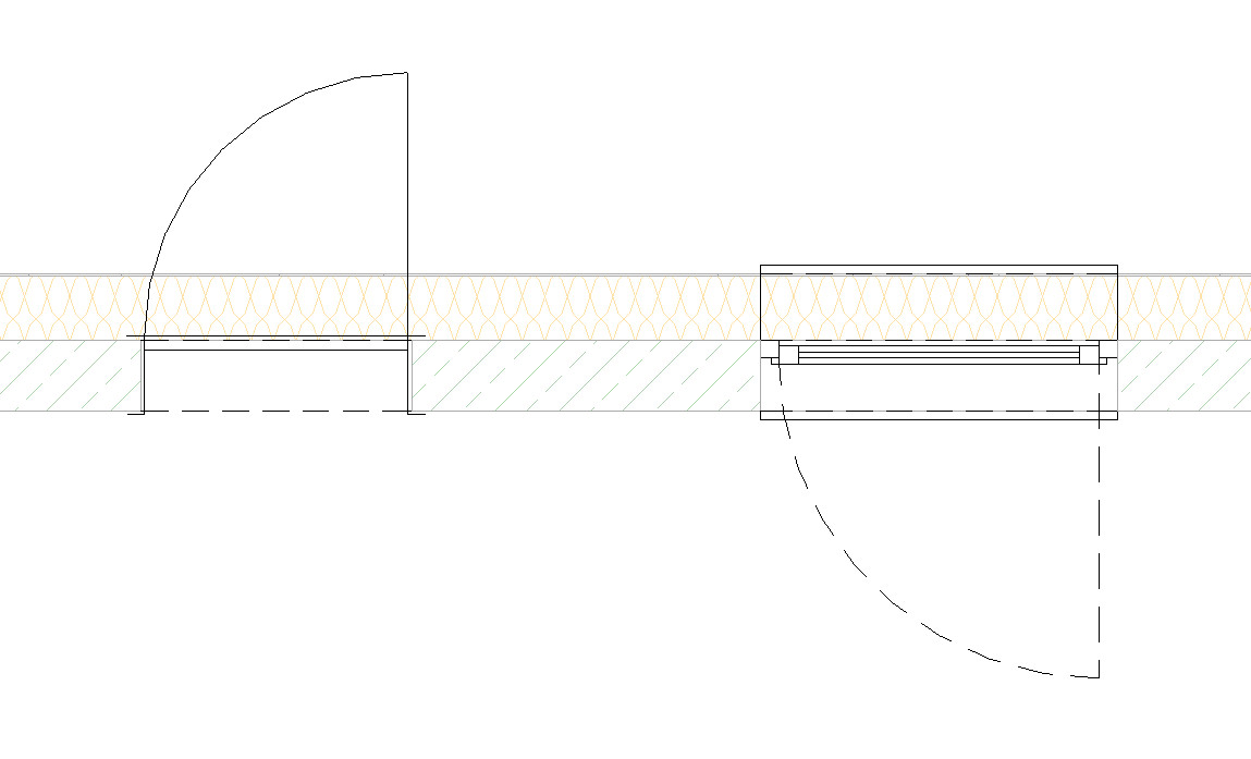
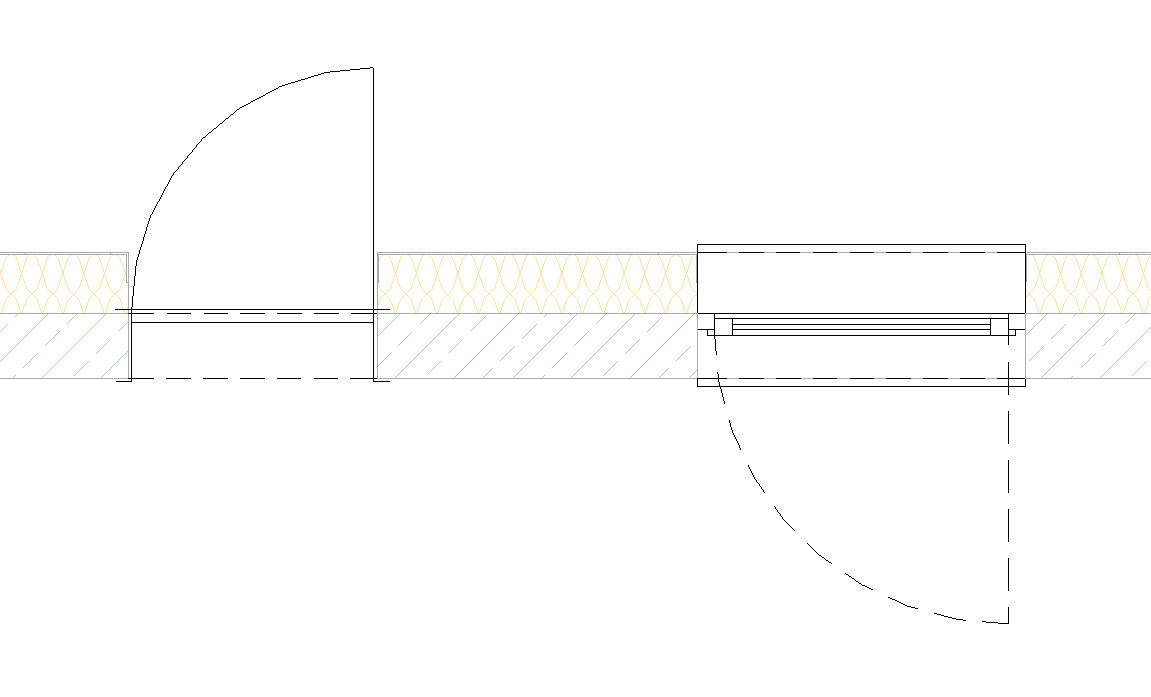
The wall structure should consist solely of the insulation layer.
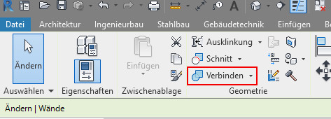
Corrections can be made using the "Up" or "Down" command.
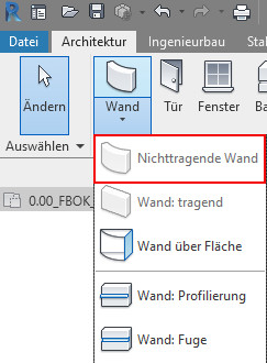
- Create a non-load-bearing wall:
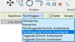
- Select the inner edge of the non-load-bearing layer:
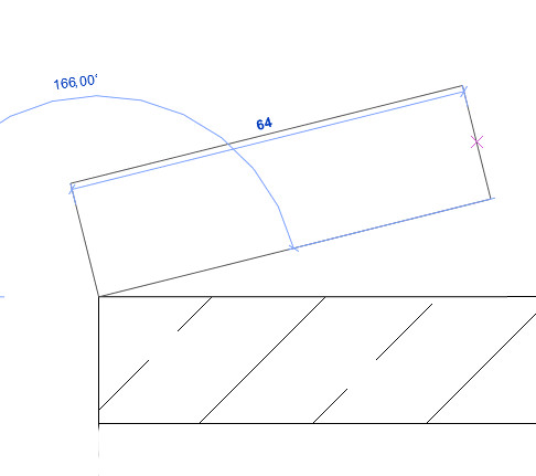
- ETICS walls must be connected to the underlying structural wall. This ensures that any openings in the structural wall are carried over to the ETICS wall (e.g., door and window openings, etc.).
No alphanumeric information is defined for the component at this stage.
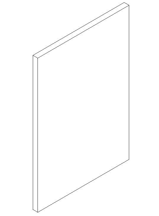
Graphical representation:

Plan view
Model representation
Plan view
Model representation

Plan view
Model representation
Features
Chassis number
Labeling
If applicable, the wall assembly number and, if applicable, the fire resistance rating are labeled during this phase.
During this phase, all information relevant to the tender is added to the component.
Graphical representation:
Plan view
Model representation
Plan view
Model representation
Plan view
Model representation
Features
Costs: ÖNORM B1801 classification, DIN KVPAPGE classification, element number, eBKP-H classification, BKG classification, formwork area, component code (type comment)
Labeling
No further labels will be created during this phase.
Instructions
Architecture and AVA are typically responsible for providing this data and ensuring its integration.