Heating and cooling units are responsible for regulating the temperature of a building and are usually located in mechanical rooms or on the roof. The heating and cooling load of buildings is determined by the building’s structural characteristics and the various ways the spaces are used, and is therefore a key factor in determining the size of the equipment.
Heating and cooling systems are not yet modeled in this design phase.
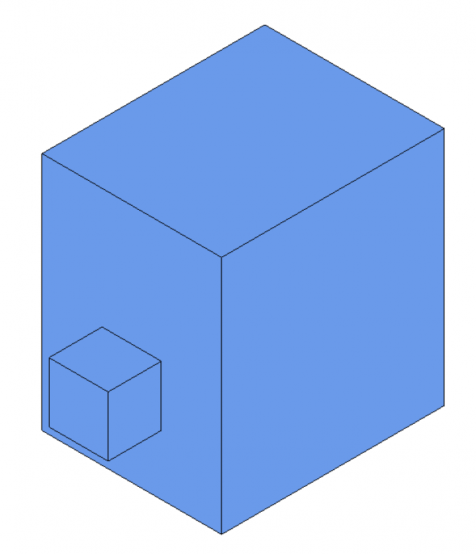
In this phase, major components in the model (e.g., heating storage tanks) are represented using placeholders (so-called "black boxes" or dummy objects). These also represent the necessary movement zones required, for example, for maintenance purposes.
Presentation
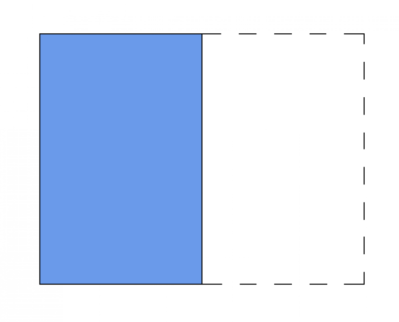
Plan view
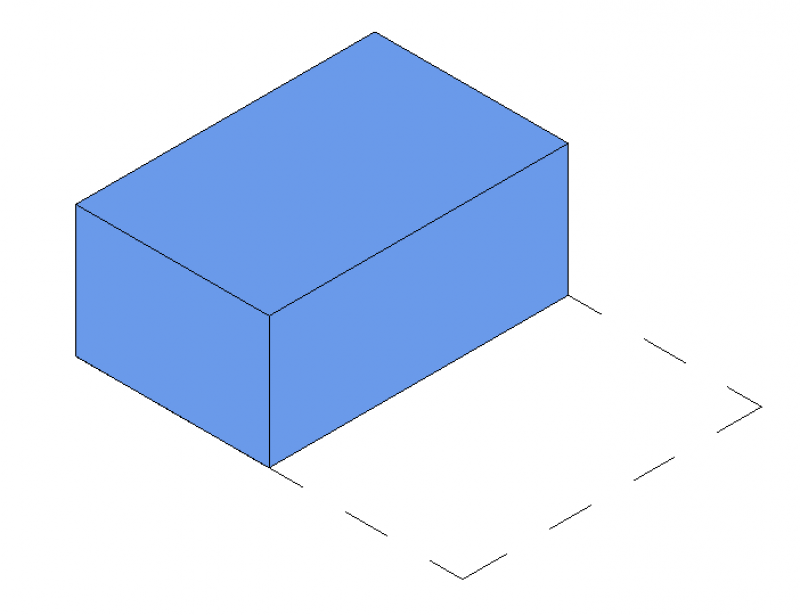
Model representation
Features
The following characteristics are defined in this phase:
- Dimensions (length, width, and height of the units)
- Dimensions of the maintenance area
- Name of the system
Labeling
During this phase, the equipment is only labeled on the plans for the relevant trade, e.g., heating.
Instructions
Create:
In this early phase, MEP components are defined as "black boxes": The button for inserting MEP components is located in the Building Services tab. The family is placed on a single layer and can then be moved manually in the section view or by entering an offset in the Properties window.
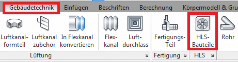
For more information, see the Autodesk Help article "Positioning HLS Components."
Presentation
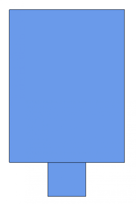
Plan view
Model representation
Features
The following characteristics must be defined in this phase:
- Heating or cooling capacity
- System type assignment
- Information on third-party systems, e.g., loads for structural design, electrical power consumption, etc.
- Numbering of units (component number/sequential number)
- Detailed sizing of unit capacities
- Zone units/split units, etc., must be added
The parameters listed above are entirely sufficient for this phase.
Labeling
During this phase, the component is labeled for the first time.
- Name
- Service
Instructions
A device can be modeled using a placeholder family that was created during the preliminary planning phase. The prerequisite for this is that the family's geometry can be edited to the extent necessary to achieve the required level of design detail.
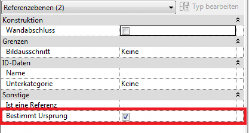
However, if the device is to be replaced with a different family, it is important to ensure that the insertion points are identical. To do this, the family to be replaced must be aligned with the currently placed family. In both families, the reference planes must be aligned so that they match in the "Defined Origin: Active" parameter.
During this phase, the drawings and models of the HLS components remain unchanged from those created during the design phase.
Presentation
During this phase, the schematics, models, and control systems for the HLS components remain unchanged from those created during the design phase.
Features
The following characteristics must be defined in this phase:
- Pressure loss of the devices according to the article "Pressure Loss Calculation"
For more information, see the article on pipe network calculations.
Labeling
At this stage, no additional text is required beyond what has already been included in the draft. However, at this stage, the height of the fixture and the distance to the ceiling and floor must be dimensioned in the section view.
Instructions
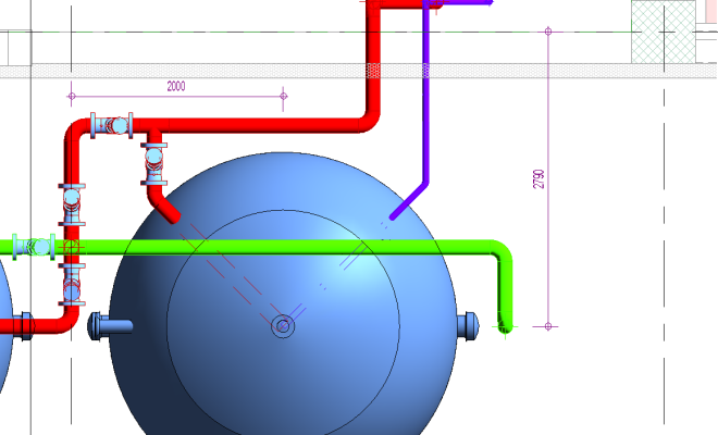
In this phase, the height of the unit and the distance from the ceiling and floor must be dimensioned in the cross-section. The length and depth are dimensioned in the floor plan. Additional information, such as item numbers in the bill of quantities, capacity, airflow rates, operating temperatures, gas pressure, etc., is described in detail and labeled in a diagram.
In addition, the devices are dimensioned on the plan.

Unfortunately, this content is available only to our Pro users.
If you'd like to read the full article, try the Pro account or become a Pro user.