Air ducts are not yet shown in this design phase.
Presentation
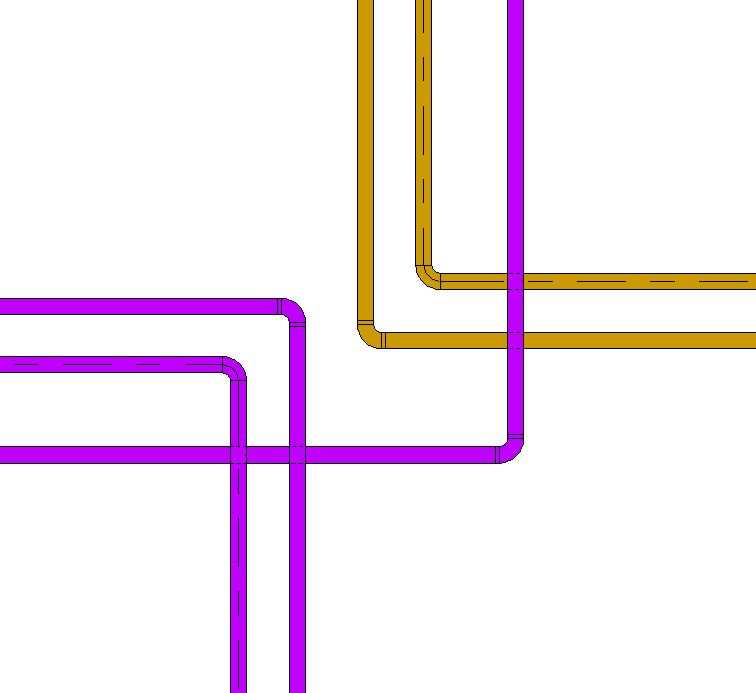
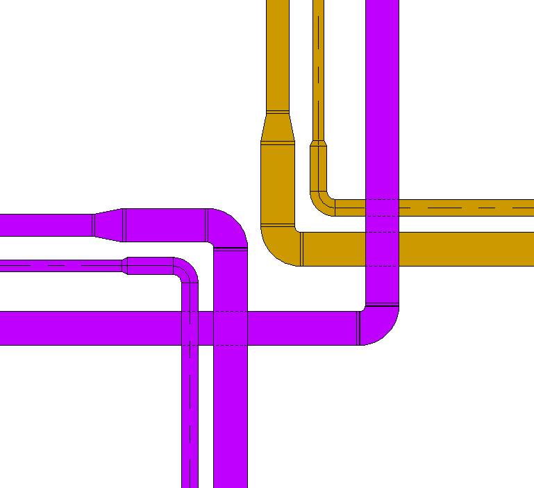
Plan view
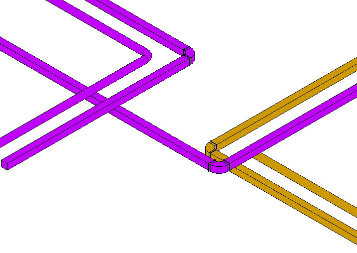
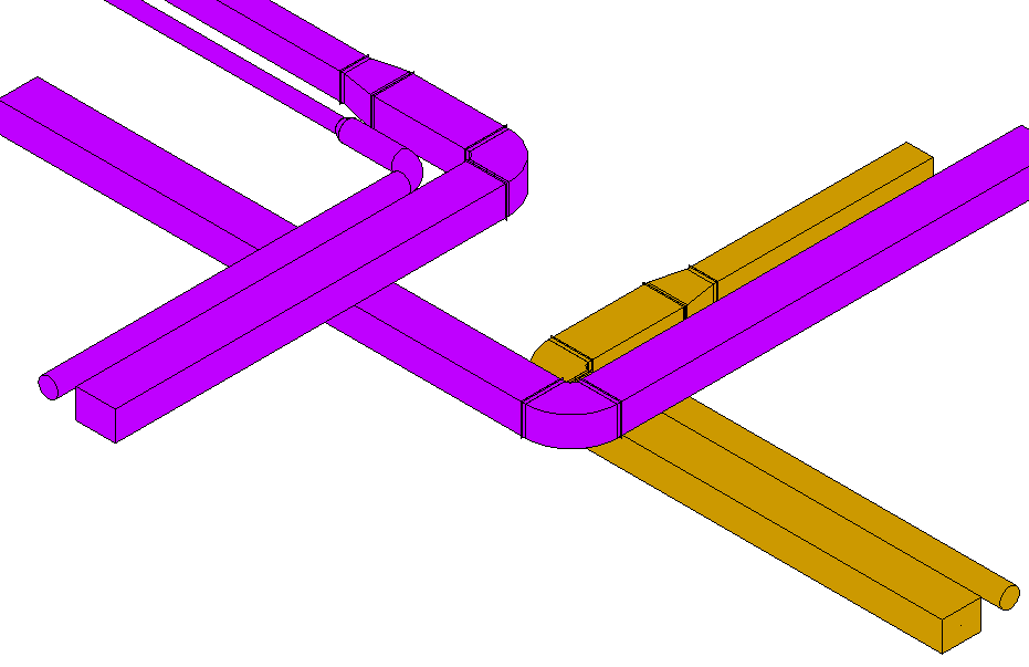
Model representation
Features
The following characteristics are defined in this phase:
- Geometry of the main routes (two-line diagram by cross-section)
Labeling
In this phase, the component is not labeled in the plan views.
Instructions
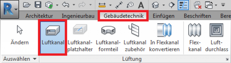
Installation of an air duct:
The button for creating the air duct is located in the Building Services tab.
Channels are offset relative to the corresponding reference plane. Only the "center-to-center" axis is used for channel alignment. A vertical offset relative to the reference plane can also be applied later by moving the channel in the section view or by adjusting the value numerically in the Properties window.
For more information, see the Autodesk Revit Help under "Air Duct."
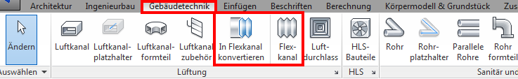
Creating a flexible channel:
The "Building Services" tab contains the button for creating flexible ducts. The "Convert Flexible Duct" button can also be used here.
The channels are offset relative to the desired reference plane, depending on their location. Only the "Center" axis is used for channel alignment. A vertical offset relative to the reference plane can also be applied later by moving the channel in the section view or by adjusting the value numerically in the Properties window.
For more information, see the Autodesk Revit Help under "Flexible Ducts."
The following families can be used for this purpose:
- Rectangular duct
- Round duct
- Flexible round duct
In this phase, the sizing is adjusted based on the ductwork calculation.
Presentation
Plan view
Model representation
Features
The following characteristics are defined in this phase:
- Geometry based on duct calculations
- Assignment of duct naming
- Air duct system assignment
- Specification of air duct insulation (fire protection cladding)
Labeling
Instructions
During this phase, the layout and model representations of the piping remain unchanged from those created in the design phase.
Presentation
During this phase, the layout and model representations of the piping remain unchanged from those created during the design phase.
Features
The following characteristics are defined in this phase:
- Adjustment of geometry based on sewer network calculations
- Sheet thickness
- Material
Labeling
The sections of the air ductwork must be labeled or indicated on the floor plan based on the ductwork network calculation and the installation heights.
Airflow: 1,380 m³/h
Installation height for round ducts: RM = -0.25 m RDUK or FBOK, depending on the predefined reference level
Installation height for rectangular ducts: KOK = -0.1 m RDUK or KUK = +2.80 m FBOK
Air flow rate: 1,380 m³/h
Installation height for round ducts: RA = -0.25 m RDUK or above FBOK, depending on the predefined reference level
Installation height for rectangular ducts: KOK = -0.1 m RDUK or KUK = +2.80 m FBOK
Instructions
You can avoid conflicts by using Revit's clash detection tool. For more information, see "Clash Detection" in Revit 2017.
In this phase, the run lengths of straight air ducts are defined. A straight air duct element can be split using the Split command.
To adjust the geometry of air ducts and fittings to the fabrication dimensions, refer to the Autodesk Revit guide "Converting General Parts to Fabrication Parts" in Revit 2017.
Additional notes for design and installation planning:
Manufacturing fixtures can be placed on the straight section of molded part extensions.
For more information on this topic, see "Placing Fabrication Brackets in Revit V2017."
In MEP fabrication modeling, parameters are available for fabrication parts. For more information, see "Instance Parameters for MEP Fabrication Parts in Revit 2017."
You can adjust the routing of air ducts in an existing duct system. For more information on modifying routing solutions, see Revit.

Unfortunately, this content is available only to our Pro users.
If you'd like to read the full article, try the Pro account or become a Pro user.