Plumbing pipes are not shown at this stage.
During this phase, the plumbing pipes are modeled for the first time.
Depending on the project scope, it may also be the case that the piping is shown only as a route here and is not modeled in 3D until the design phase.
Presentation
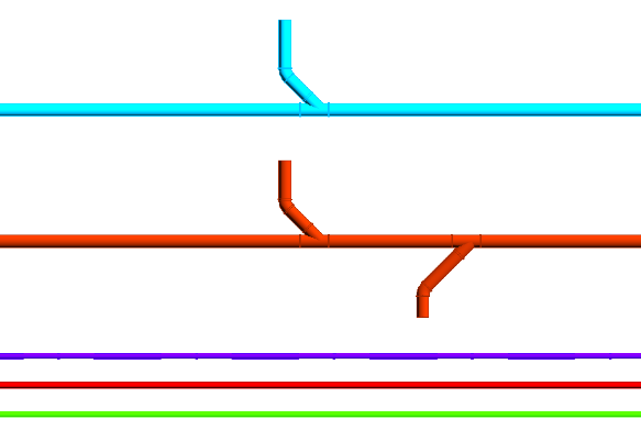
Plan view
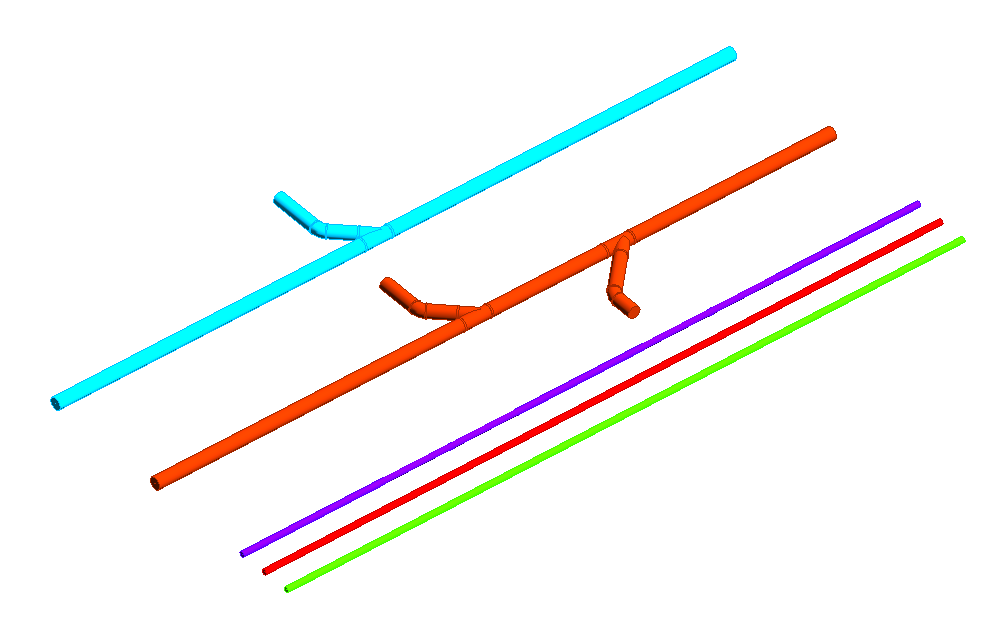
Model representation
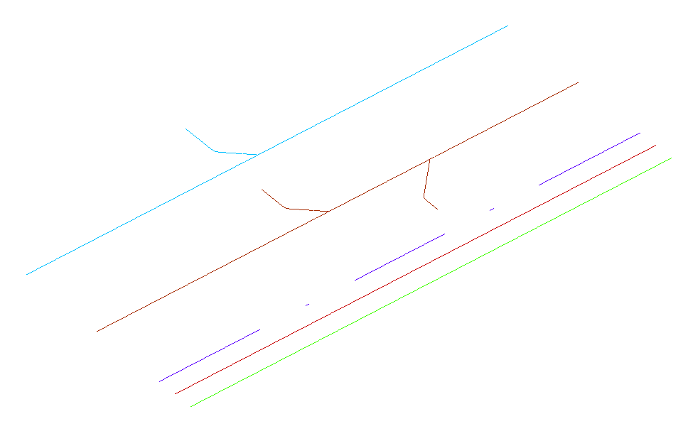
img_23
Features
The following characteristics are defined in this phase:
- Geometry of the main routes
Labeling
At this stage, the component is not yet labeled in the plan view.
Instructions
When modeling plumbing pipes in Revit, it is essential to distinguish between supply and drain pipes.
The pipe routing is set up before modeling begins. For more information, see Revit V2017.
On the Building Systems tab, in the Plumbing and Piping group, you will find commands for creating horizontal and vertical pipes, as well as pipes with a slope. For more information, see "Piping" in Revit V2025.
Specific dimension ranges can be assigned to segments and fittings to be used for pipe routing. For more information, see "Setting Pipe Routing Preferences" in Revit V2025.
Interests:
A slope can be added to the pipe either during modeling or afterward.
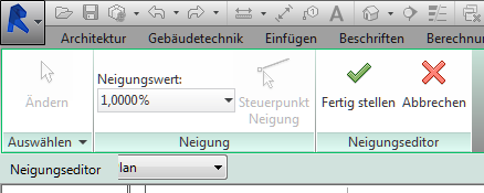
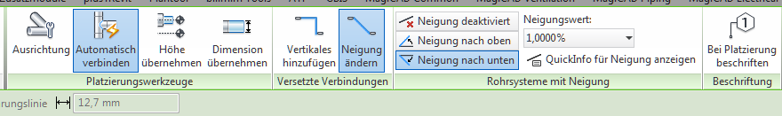
1. While modeling:
Using the Pipe command, you can select the slope and direction in the modeling options.
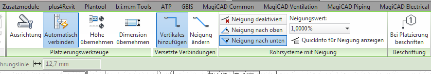
Pipes can now be drawn at the set angle until the option is manually changed again; this means you need to be careful when drawing or coordinating multiple trades at the same time.
2. Addition made later:
First, identify the desired pipe section and select the slope value in the "Slope" modeling option.
The reference point (red arrow on the pipe) indicates the point from which the slope should extend upward.
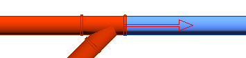
The control point can only be defined at open ends and drop points. If both ends of the pipe are connected to other pipes or components, the slope cannot be applied to the pipe.
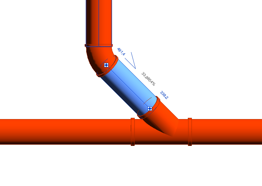
Adjusting the angle of the pipe itself after installation:
If the inclined pipe section is selected (the current slope is displayed directly on the pipe), you can change the slope directly on the pipe by selecting the number.
Note:
- A negative sign changes the direction of the slope
- The small angle symbol before the number indicates the orientation
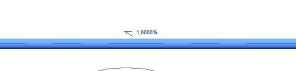
If the number is grayed out, both pipe ends are firmly connected, and the angle can only be changed later by cutting the pipe.
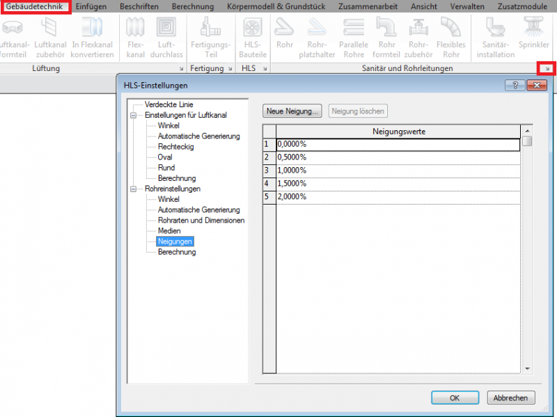
Preset angles:
Various pipe slopes ranging from 0% to 2% are available as preset values for modeling. If any slopes are missing, they can be added in the Manage tab > MEP Settings > HVAC Settings or in the
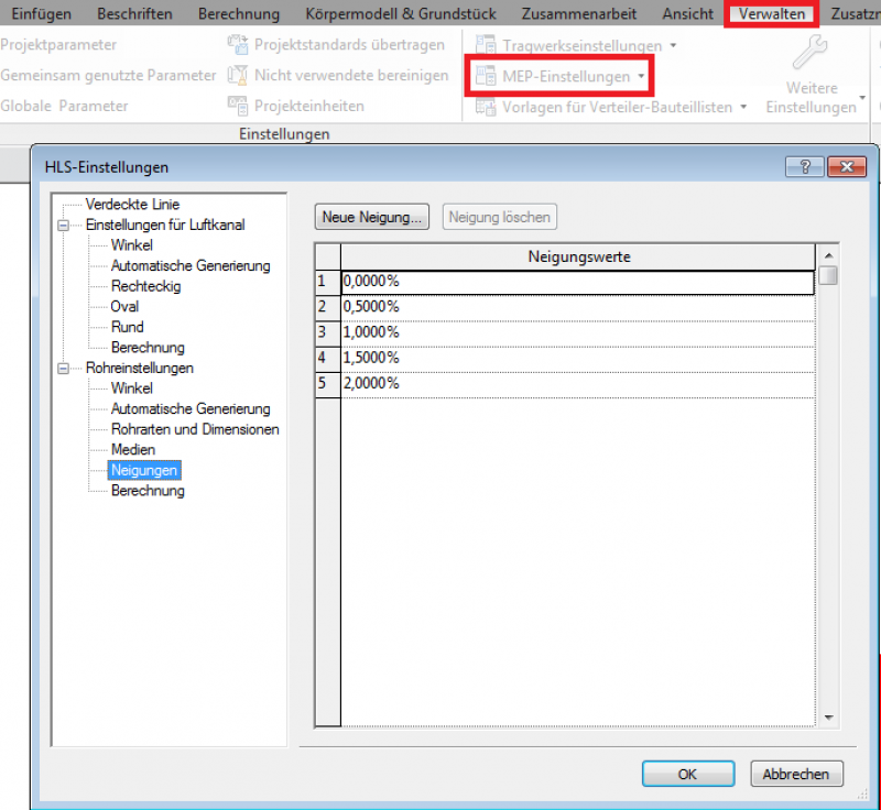
Add the "Building Services" tab under "Plumbing and Piping" > "HLS Settings".
Archicad Content
Presentation
The plan and model are presented in the same way as in the preliminary planning phase.
Features
The following characteristics are defined in this phase:
- Geometry based on piping network calculations
- Plumbing components
- Pipe insulation
- Assignment of piping systems
- Pipe material
- Interfaces with other trades
- Possible update of pipe series
The pipe series type (routing) can be updated in the project using pre-defined pipe series.
To select the entire pipe routing, press the Tab key > Edit Group > Change Type. For more information, see "Specify Routing Preferences for Pipe" in Revit V2017.
Labeling
The following information has been added:
- System Name (Abbreviation)
- Dimension
- Pipe Slope
Ideally, pipes should be labeled using a family that retrieves the necessary information from the "Pipes" parameter and the element properties.
A slope value can be labeled as a pipe gradient using the Slope Elevation command. For more information, see "Slope Elevations" in Revit V2017.
Instructions
Wastewater and pipe network calculations should be performed using Excel or the Solar-Computer module. For more information, see the Solar Pipe Network Calculation Guide.
Note: Once wastewater networks have been exported and calculated in Solarcomputer, they cannot be reimported into the model.
During this phase, the layout and model representations of the piping remain unchanged from the draft version.
Presentation
At this stage, the layout and modeling of the pipes and pipe fittings remain the same as in the preliminary design phase.
Features
The following characteristics are defined in this phase:
- Adjustment of the geometry based on a detailed piping network calculation
- Object number based on detailed piping network calculation
- Detailed coordination with other trades
- Reference plane
- Offset
- Weight
Labeling
At this stage, the labels should be made more detailed, and the components should also be dimensioned.
Ideally, pipes should be labeled using a family that retrieves the necessary information from the Pipe parameter and the element properties.
[insert new content here]
Instructions
General tips for working with slopes:
- First, mark the run of the main drain pipe from the last plumbing fixture to be connected, using the specified slope, all the way to the drain outlet.
- Check the elevation profile of the line in the section view, and then draw the individual branch lines with their slopes up to just before the main line.
- Then select the Pipe command Change Slope and connect the pipe to the main run at a 45° angle in the direction of flow.
This connects the pipe to the manifold, regardless of the elevation of the connecting pipe (Revit automatically selects the angle for the connector).
Entire sub-networks and pipe runs can also be adjusted to a new slope. To do this, it is important that the last section of pipe remains loose.
- Select a sub-network and set an inclination value using the Inclination dialog box
- Depending on the complexity of the sub-network, Revit determines whether the operation succeeds or fails

Unfortunately, this content is available only to our Pro users.
If you'd like to read the full article, try the Pro account or become a Pro user.