Glass roofs are a special type of roof; in principle, the same guidelines apply as for other roofs. Depending on the software, there are different tools available for creating glass roofs. Revit, for example, offers a dedicated tool for this purpose, whereas in ArchiCAD, glass roofs are primarily modeled using individual elements (e.g., panes, beams, etc.).
Glass roof: glass roofs, glass structures, openings, glazing, mullions, transoms, natural lighting
At this stage, it is not yet necessary to assign a material to the component. However, doing so can certainly be beneficial for visualization purposes.
Presentation
img_12
img_14
Features
Feature
- Type of roof structure
- Status
Parameters
- Gross floor area
- Total thickness
- Net area
- Projected area
- Dormer width
- Dormer height
- Dormer type
Outline Information
- Exterior element
- Room-enclosing element
Labeling
At this stage, the component is not yet labeled in the plan views.
Instructions
In Revit, the "glass roof" component corresponds to a "roof" system family; the type specifies the material of the infill elements and their thickness.
Roofs do not have a load-bearing option.
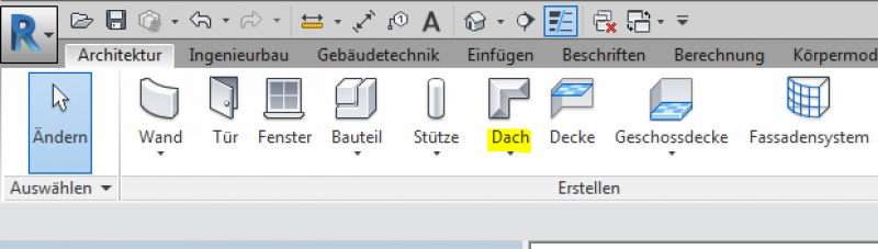
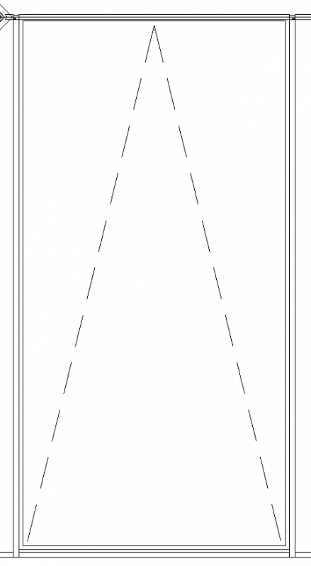
It makes sense to use the "Roof over Floor Area" option and then create the roof geometry in Sketch Mode.
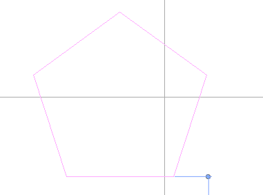
The required slope is determined by the sketch lines.
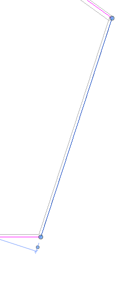
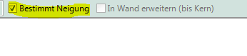
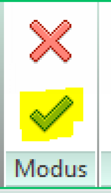
When you exit sketch mode, the roof is created.
See also Facades.
Presentation
img_12
img_18
Features
- Roof accessibility
- Fire resistance class
Parameters
- Roof pitch
- Volume
Outline Information
Labeling
At this stage, the component is not yet labeled in the plan views.
Instructions
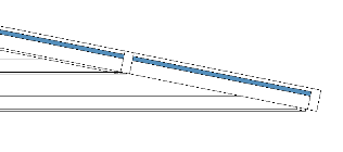
During this phase, the glass roof will be divided into smaller sections. This is illustrated using the facade grid.
ArchiCAD Content
During this phase of the design process, the building model is updated to include structural engineering and building physics data, as well as openings and windows.
Presentation
img_12
img_18
Features
- Sound insulation class
- U-value
Outline Information
Labeling
At this stage, the component is not yet labeled in the plan views.
Instructions
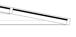
The roof element is selected and then decoupled from it.
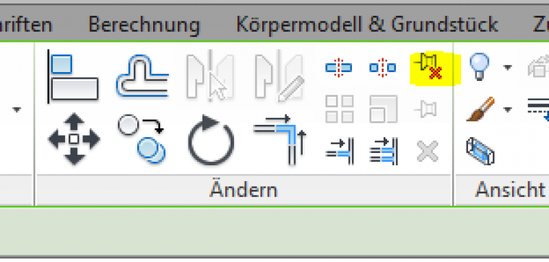
After this step, the element is displayed accordingly.
ArchiCAD Content
Presentation
Features
Labeling
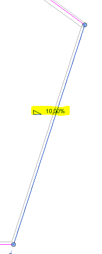
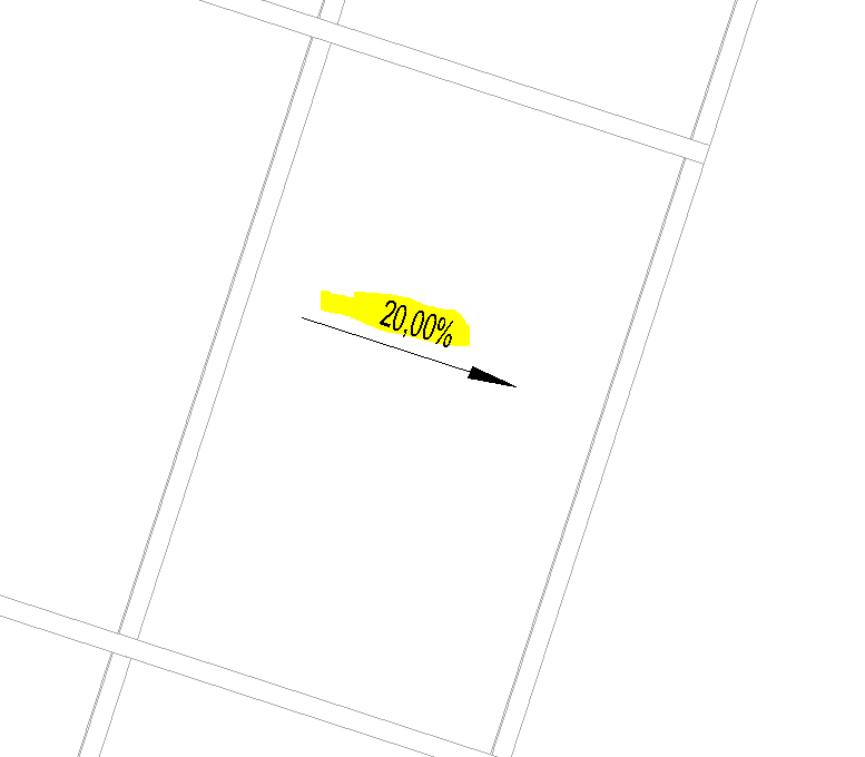
For this phase, the angle must be marked on the component.
Instructions
The fire safety specifications must be incorporated into the architectural model.
During this phase, information required for the request for proposals is added to the project.
Presentation

img_37
img_18
Features
The following characteristics must be defined at this stage:
Costs:
- Correspondence to ÖNORM B1801
- Classification DIN KVPAPGE
- Element No.
- eBKP-H Classification
- ATP-BKG assignment
- ATP Component Code (Type Comment)
- Reference
Parameters
Outline Information
Labeling
For this phase, the architectural team must label the element dimensions, the top edges, the bottom edges, and the slope.
Instructions
In this phase, the architecture is used to further refine the geometry. The AVA provides the alphanumeric data for the bill of quantities and the request for proposals.
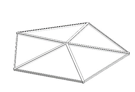
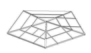
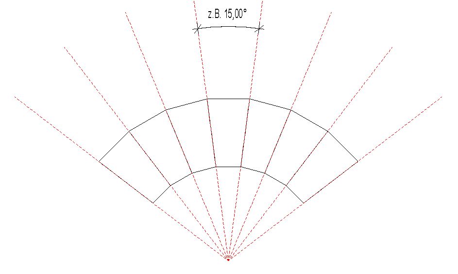
Radially arranged posts
By default, Revit always attempts to arrange the mullions and transoms of a glass roof or facade at right angles to one another. However, if a glass roof or facade element is generated from a solid, this behavior can be overridden.
Instructions:
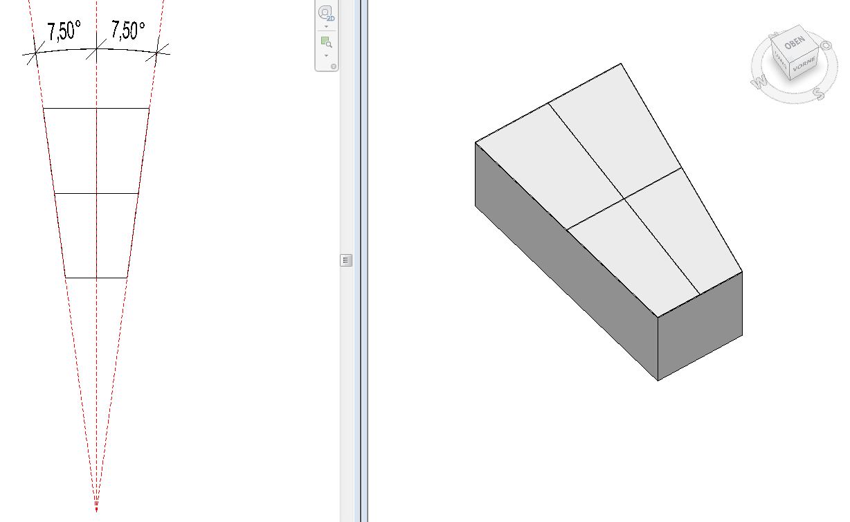
Before beginning the modeling process, the glass roof must be divided into individual repeating sections based on a sketch.
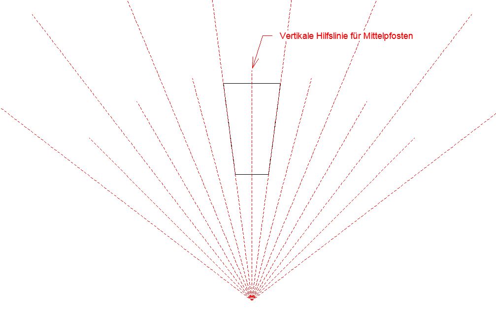
Each sector should have no center posts, or at most one.
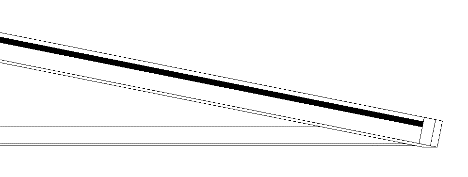
For the version with a center post, make sure that it is perfectly vertical in the sketch.
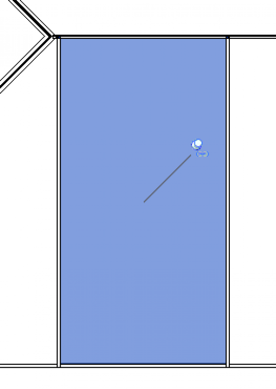
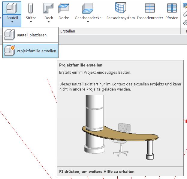
Next, use the "Part --> Create Project Family" command to create a solid as an auxiliary feature.
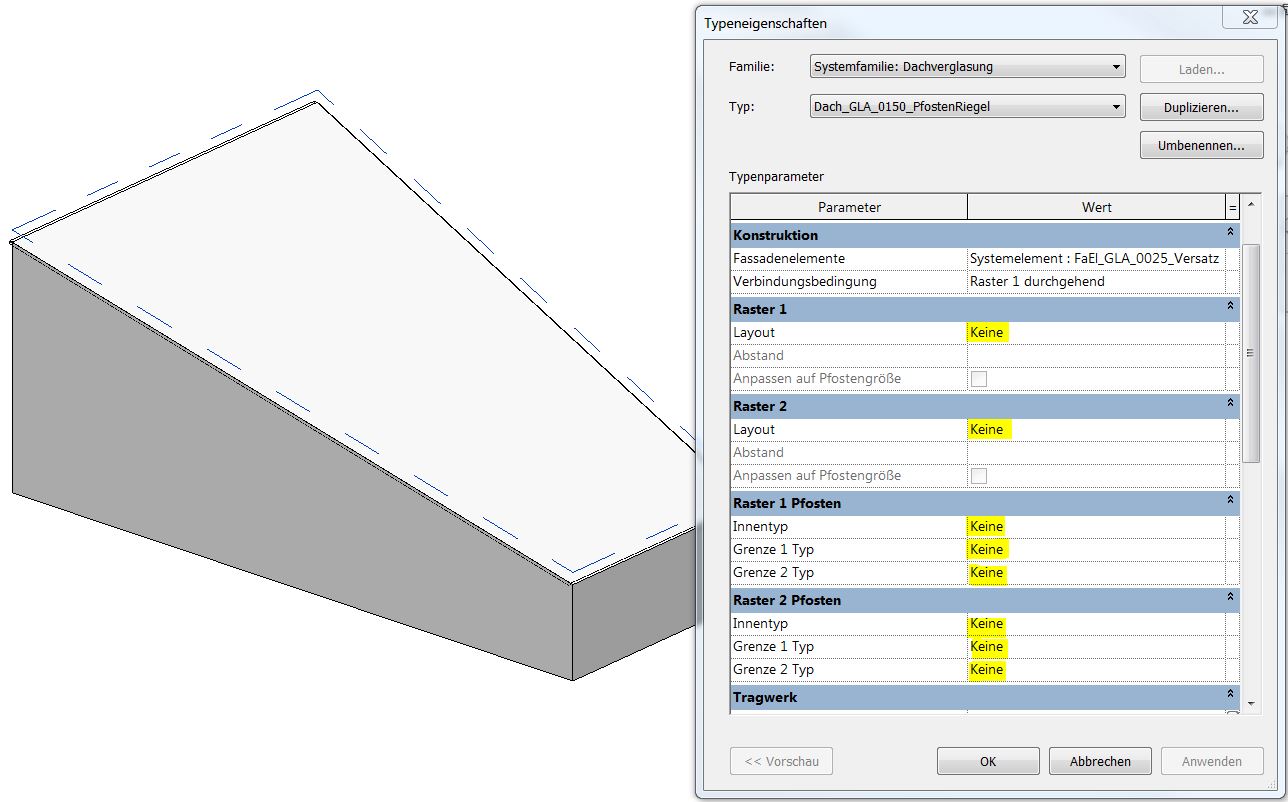
A glass roof is generated on top of the body using the "Roof over Surface" command.
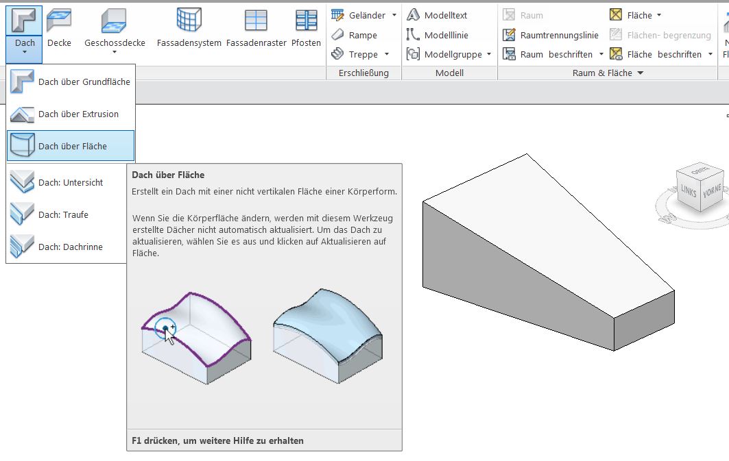
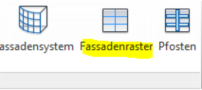
The selected roof type should have the "None" grid setting.
All posts should also be set to "None."
This may be followed by a subdivision using the "Facade Grid" command
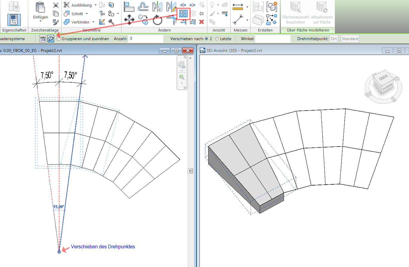
Next, use the "Row --> Radial" command to copy the glass roof section the desired number of times.
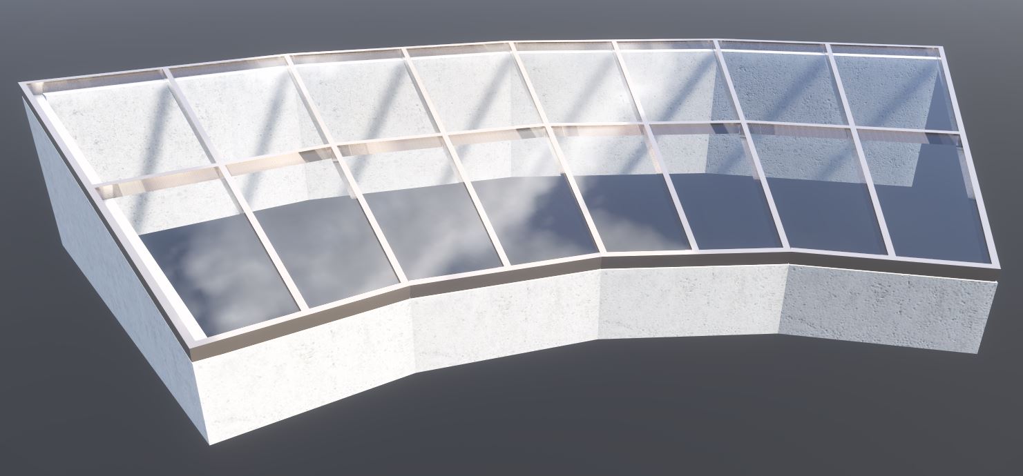
Finally, all posts are added using the "Facade Posts" command.

Unfortunately, this content is available only to our Pro users.
If you'd like to read the full article, try the Pro account or become a Pro user.