Piping systems, also known as routings, are responsible for distributing the treated medium (air, water, etc.) throughout a building. Piping systems are classified by material. Depending on the building trade, only certain materials may be used to avoid affecting the medium inside the pipe.
Video tutorial
This video explains the most important features:
To load this content, you need to allow the YouTube service.
Pipes are not yet shown in this phase.
Presentation
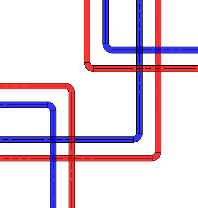
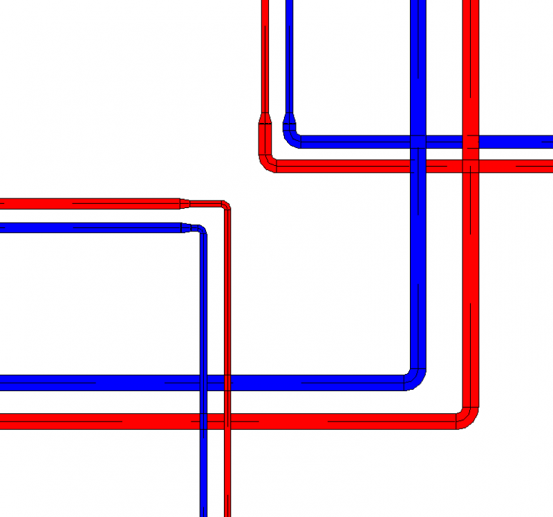
Plan view
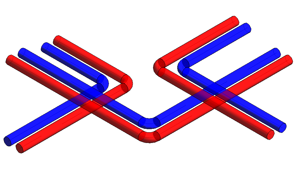
Model representation
Features
The following characteristics are defined in this phase:
- Geometry of the main routes (a two-line diagram by cross-section)
- Operating temperature as low and/or high temperature, e.g., supply VL/return RL 70/50°C, 60/40°C
- Medium, e.g., water, gas
Labeling
In this phase, the component is not labeled in the plan view.
Instructions
Manufacturing the pipe:
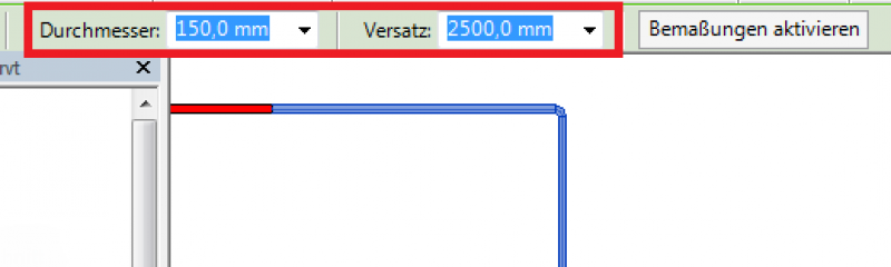
The "Building Services" tab contains the button for creating piping > Pipe. A pipe is offset relative to a plane. Only the center axis is used for pipe alignment. A height offset relative to the reference plane can also be adjusted later by moving the pipe in the section view or by entering a numerical value in the Properties window.
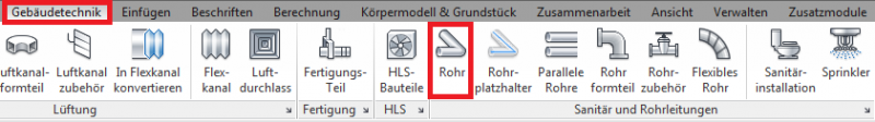
For more information, see also Revit V2017 Pipes.
Manufacturing a flexible tube:
The "Building Services" tab contains the button for creating flexible pipes > Flexible Pipe. A flexible pipe is offset relative to a plane. Only the center axis is used for pipe alignment. A height offset relative to the reference plane can also be applied later by moving the pipe in the section view or adjusted numerically in the Properties window.
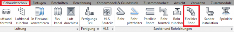
For more information, see also Revit V2017 Flexible Pipe.
The following types of piping systems are available:
- Stainless steel tube
- Steel pipe
- Plastic pipe
Presentation
Plan view
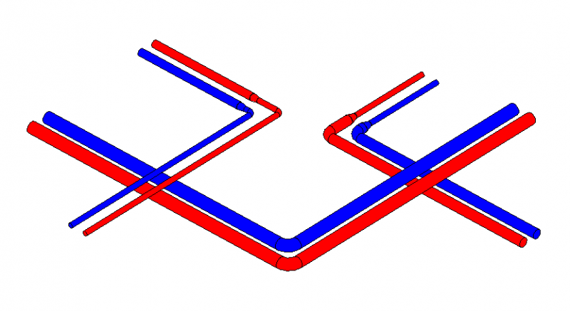
Model representation
img_12
Features
The following characteristics must be defined in this phase:
- Geometry based on the piping network calculation
- Assignment of pipe line designations
- Pipe system assignment
- Specification of pipe insulation
- Operating temperature specifications
Labeling
The following information must be included in this planning phase:
- Dimension
- Pipe system
Instructions
Cross-sectional changes to the existing main routes are made using the "Split Element" button under "Edit."
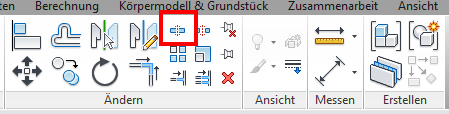
First, select the pipe section to be edited, then move the mouse pointer to the last pipe segment. Right-click to select the highlighted pipe section. You can now adjust the channel cross-section.
During this phase, the layout and model representations of the piping remain unchanged from those created during the design phase.
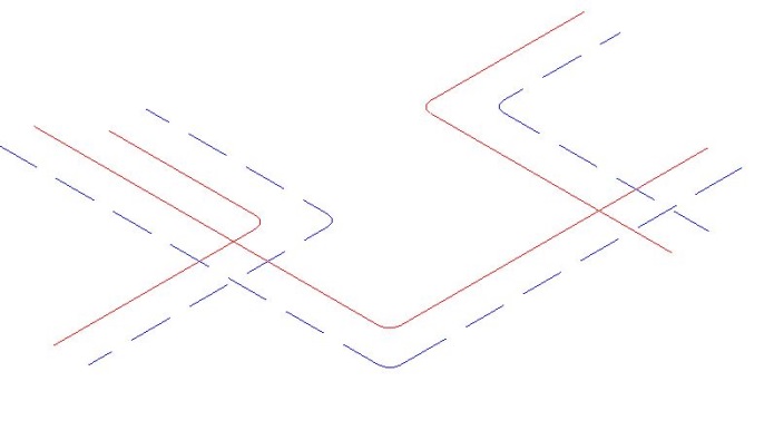
Presentation
During this phase, the layout and model representations of the piping remain unchanged from those created during the design phase.
Features
The following characteristics are defined in this phase:
- Adjustment of geometry based on pipe network calculations
- Pipe thickness
- Material
Labeling
The pipeline routes must be labeled or indicated on the floor plan based on the piping network calculation and installation heights.
Flow rate: 1.38 l/s
Speed: 0.29 m/s
Pipe installation height: RM = -0.25 m RDUK or FBOK, depending on the predefined reference level
Flow rate: 1.38 l/s
Speed: 0.29 m/s
Pipe installation height: RA = -0.25 m RDUK or FBOK, depending on the predefined reference level
Instructions
You can avoid conflicts by using Revit's clash detection tool. For more information, see "Clash Detection" in Revit 2017.
In this phase, the run lengths of straight air ducts are defined. A straight air duct element can be split using the Split command.
To adjust the geometry of air ducts and fittings to the fabrication dimensions, refer to the Autodesk Revit guide "Converting General Parts to Fabrication Parts" in Revit 2017.
Additional notes for design and installation planning:
Manufacturing fixtures can be placed on the straight section of molded part extensions.
For more information on this topic, see "Placing Fabrication Brackets in Revit V2017."
In MEP fabrication modeling, parameters are available for fabrication parts. For more information, see "Instance Parameters for MEP Fabrication Parts in Revit 2017."
You can adjust the routing of pipes in an existing piping system. For more information on modifying routing solutions, see the Autodesk Note

Unfortunately, this content is available only to our Pro users.
If you'd like to read the full article, try the Pro account or become a Pro user.