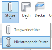
Non-load-bearing supports, or decorative supports, are primarily used for design and decorative purposes. They are also used to conceal elements such as conduit runs. Regardless of the material used, they do not bear any load, which distinguishes them from structural columns.
Search terms: cladding, sheathing, coating, covering
Modeling is not yet necessary at this stage.
Presentation
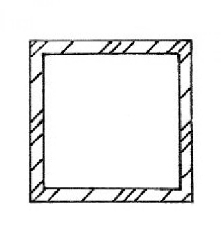
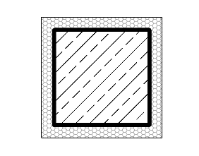
Cross-sectional view
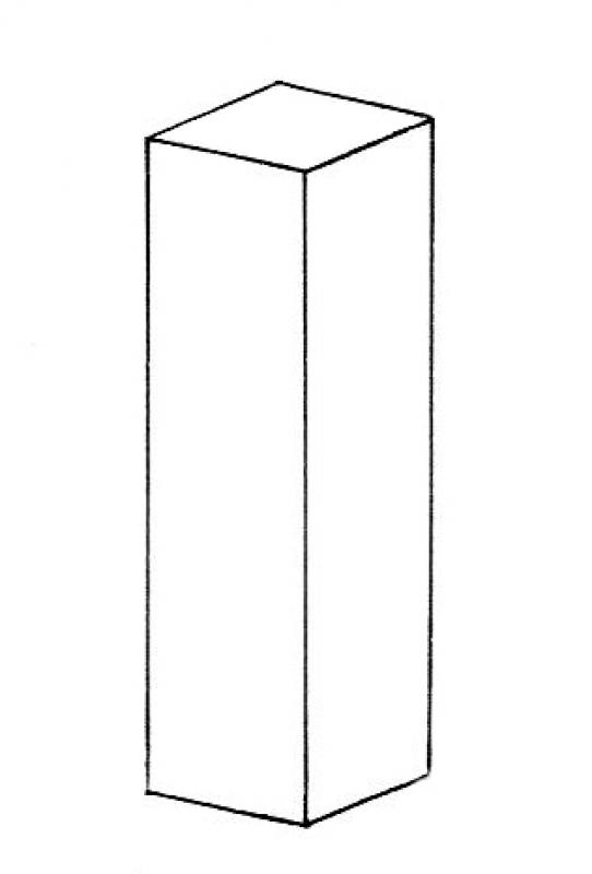
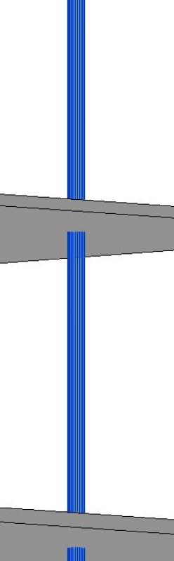
Model representation
Features
Feature
- Status
Parameters
- Wide support
- Gross volume of support
- Rotation angle
- Total surface area of support
- Length of support
- Lateral surface area of support
- Support slope
- Net surface area
- Cross-sectional area of column
- Radius of column
- Depth of column
Outline Information
- Outer element
- Position in the grid
Labeling
No label is required at this time.
Instructions
Create
In industrial construction, formwork props are often modeled using the "Non-load-bearing prop" tool as early as the preliminary planning stage.
The same applies here: columns should be modeled as single-story structures.
Reference levels
- bottom: top edge of floor / top edge of rough ceiling
- top: bottom edge of sloped ceiling / bottom edge of rough ceiling
Autodesk's guide to modeling non-load-bearing columns can be found here: Non-load-bearing columns
Example
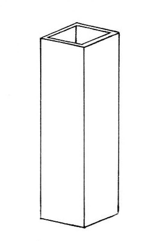
An example of non-load-bearing supports is the cladding of vertical pipes or ducts in industrial construction.
Presentation
Cross-sectional view
Model representation
Features
- Earth-touching element
Parameters
Outline Information
Labeling
No labels are required at this stage.
Instructions
If non-load-bearing columns are to be modeled during the preliminary design phase, refer to the instructions for the preliminary design phase.
Presentation
Cross-sectional view
Model representation
Features
Labeling
During this phase, the component is labeled.
When selecting a labeling family, be sure to assign it to the correct category. For non-load-bearing columns, we recommend choosing a cross-category label.
Instructions
Due to widely varying regulatory requirements, there are no universal guidelines for this phase. The general guidelines for quality assurance and error prevention apply:
- You should always use label families instead of text.
Presentation
Cross-sectional view
Model representation
Multi-story formwork props
If columns have been modeled as multi-story elements, they can be split later using the "Split Element" command.
To do this, draw a line through the familiar symbol on a floor plan:

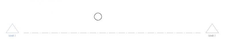
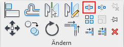
With the section open, use the Split Element (SL) command to split the column at the desired location.
Important:
After dividing the column into individual elements, please delete the "center section," which may still be located in the ceiling. Otherwise, an error message will appear during the model validation process due to the overlap.
In addition, after splitting a column using the Split Element command, check the plane assignment of the subelements in the Properties window.
Note: The "Separate with space" command, however, does not work.

See also Autodesk Help: Splitting Elements
Column covers
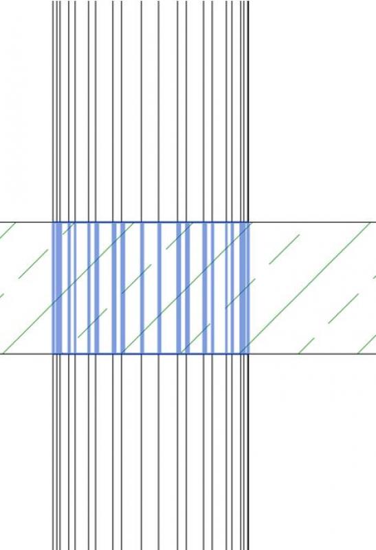
Column cladding and cladding for utility shafts, which are classified as panel/drywall construction, are modeled as partition walls.
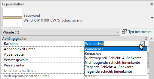
Care must be taken to ensure that the baseline of the partition wall/cladding is set at the outer edge of the non-load-bearing layer.
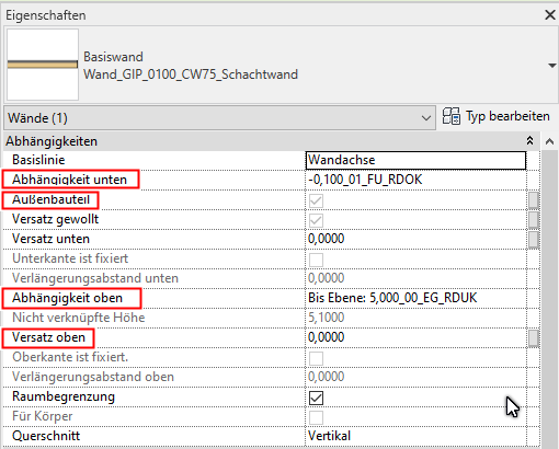
Check the clearances at the top and bottom; generally, the offset should be set to 0.00 in each case.
Copy columns
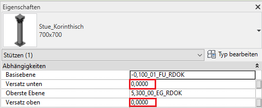
If columns are copied floor by floor, the reference planes and the offset must be checked and corrected if necessary. This setting is usually incorrect after copying. The offset must be reset to 0.00 unless an offset is explicitly desired, since the relative room height of the original column is copied along with it.
Example:
Support to be copied on the ground floor:
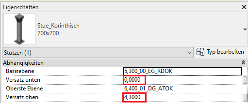
duplicated column on the floor above:
No tips and tricks

Unfortunately, this content is available only to our Pro users.
If you'd like to read the full article, try the Pro account or become a Pro user.