The installation work includes all electrical components installed in cast-in-place concrete or precast concrete elements (walls, ceilings, floors, foundations, etc.) such as
: -
Conduit - Outlets
- Flush-mounted boxes for switches/outlets
- Recessed lighting fixtures
- Etc.
The inlays are primarily drawn in 2D using detail lines; alternatively, empty tubes may be used.
All openings (grommets, junction boxes, channel bodies, etc.) are also modeled using detail lines or as 3D families.
Among the pipe types, a specific pipe routing was created for the electrical system, which includes the designation "empty conduit."
This is used for:
- Concealed conduit
- Surface-mounted conduit (not covered in this article)
- Plastic
- Aluminum
- Stainless steel
Graphical representation
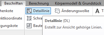
The inlays are displayed graphically using the Label > Detail Line toolbar.
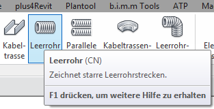
Alternatively, pipe families can be drawn using the Building Services > Empty Pipe toolbar.
Graphical interface
No drawings are required at this stage of the project.
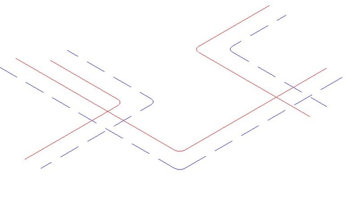
In this phase, the piping is shown on the plan and in the top view, and the model is displayed in 3D.
Isometric view:
Features
The following characteristics are defined in this phase:
- Pipe size (type, size)
- Outlet points with dimensions
Labeling
There are no special provisions.
No plan is required for this phase of the project.
The representation of the conduit system in the plan or in 3D is consistent with the design.
It is necessary to coordinate the conduit installation with the reinforcement and adjust it as needed. The outlet locations must also be coordinated with the electrical and building services trades > clash detection.
Features
No additional attributes need to be defined.

Unfortunately, this content is available only to our Pro users.
If you'd like to read the full article, try the Pro account or become a Pro user.