An electrical power balance must be prepared for each building, and the required power supply must be defined. Depending on the type, purpose, and size of the building, the type, number, and size of the necessary transformers (abbreviated: trans) as well as the associated rooms are defined in collaboration with the architectural team and the utility company (EVU) in accordance with the latest versions of the relevant standards.
Although transformers are not yet modeled in this phase of the project, the necessary transformer rooms should be planned in coordination with the architectural design.
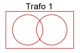
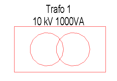
In this phase, the transformers are plotted in transformer boxes.
Presentation
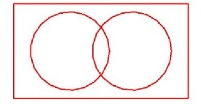
Plan view
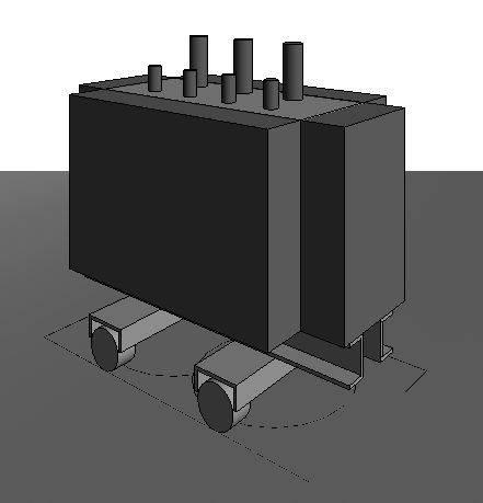
Model representation
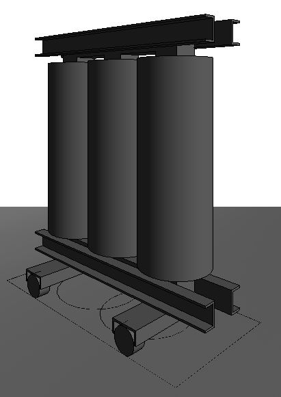
img 11
Features
The following characteristics must be defined in this phase:
- Loads for structural design
- Length/Width/Height
- Apparent power
- Model number
- Wheelbase
- Short-circuit voltage uk
- Rated primary voltage
- Secondary voltage
Labeling
During this phase, the following information is labeled on the system:
- Asset Name
- Asset number
Instructions
In Revit, transformers belong to the Electrical Equipment family category.
The transformers are created in Revit using the Elau_Oil_Transformer and Elau_Dry_Transformer families in the Building Services tab under Electrical Equipment.
When you select the desired family from the Properties drop-down menu, Revit prompts you to specify where the family should be placed. Use the Modify/Place tab to position the transformer using the Place on Surface command.
Families can be placed on a wall or at a work plane. This way, when the wall is moved, the family moves along with it. This is particularly useful when making architectural changes.
On average, the family's positioning can be checked and adjusted if necessary.
During this phase of the project, the drawings and models of the transformers remain unchanged from those created during the preliminary design phase. However, the sound power level must be specified in the technical report.
The energy law filing shows the transformers in as-built quality.
During this design phase, the specific transformer types are selected.
Presentation
In this phase of the project, there is no difference from the plans and models presented in the design phase.
Features
In addition to the existing features, the following information will be added:
- Medium voltage
Labeling
The following information will be added to the existing labeling:
- Rated primary voltage
- Short-circuit voltage
- Taps
- No-load losses
- Short-circuit losses
- Sound power level
- Apparent power
Instructions

Unfortunately, this content is available only to our Pro users.
If you'd like to read the full article, try the Pro account or become a Pro user.