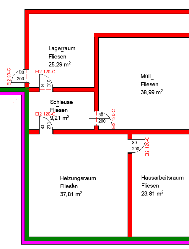
Strictly speaking, fire and smoke compartment boundaries are not actual model elements; nevertheless, they represent an important structural definition and must be represented in a model.
There are two methods available for defining fire and/or smoke compartment boundaries. In the first method, the compartment boundaries are represented by lines; in the second, modeled walls and their parameterized fire protection properties are used to graphically highlight the boundary lines. Which method is preferable depends, among other things, on the required scale.
Fire and smoke compartment boundaries are defined no later than the design phase. Their implementation in the model is typically handled by the architectural team.
Instructions
Section boundaries should be created using model lines rather than detail lines.
Thus, the section boundaries are independent of the view, since they are part of the model.
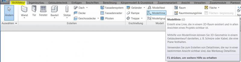
Detail lines would have to be copied into every required view, which always carries the risk of inconsistencies in the planning status across the individual views.
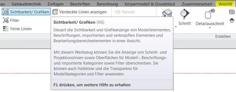
The visibility and appearance of the model lines can be controlled individually in each view via the Visibility/Graphics menu.
Fire and smoke compartment boundaries can be created using the Line tool. The lines are assigned to a layer and a pen to control their visibility and how they appear in the various section sets. In addition, you can use the graphical override rules to create additional visual effects.
Instructions
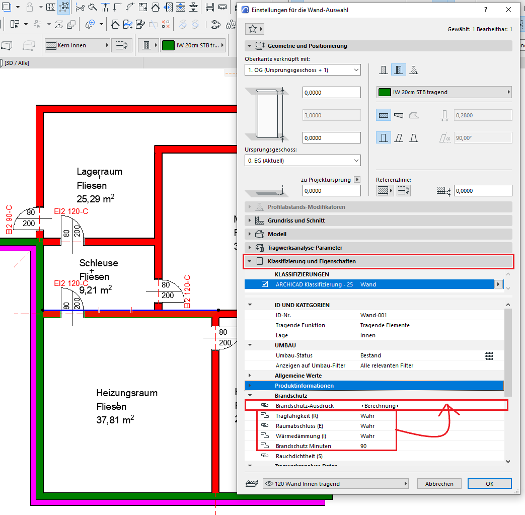
A corresponding parameter is required for the component-specific assignment of fire protection properties. The specific parameter required must be clarified with BIM Management.
The fire resistance properties are then assigned to the building elements—such as walls—based on this parameter.
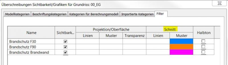
Filters are then applied based on the values of the corresponding parameter. Depending on the fire resistance rating, these filters can be used to display the building elements in different ways.
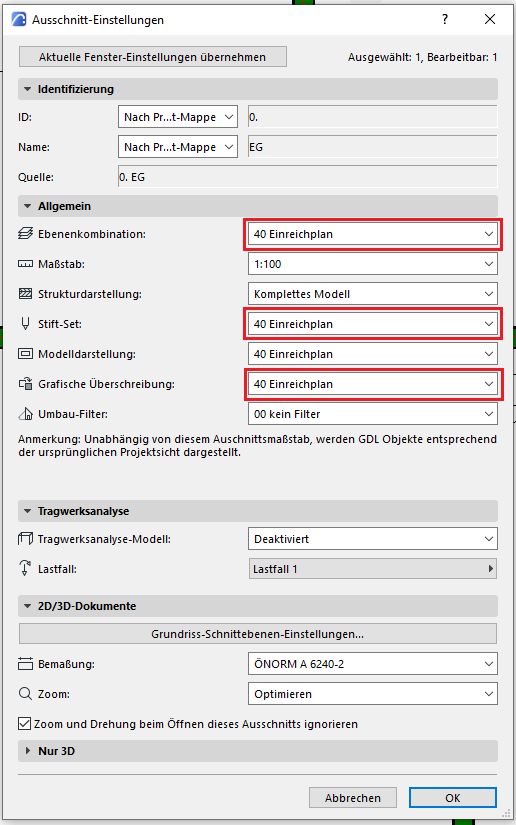
In the relevant views, the filters are loaded in the Visibility/Graphics menu and overridden graphically.
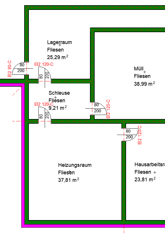
Example:
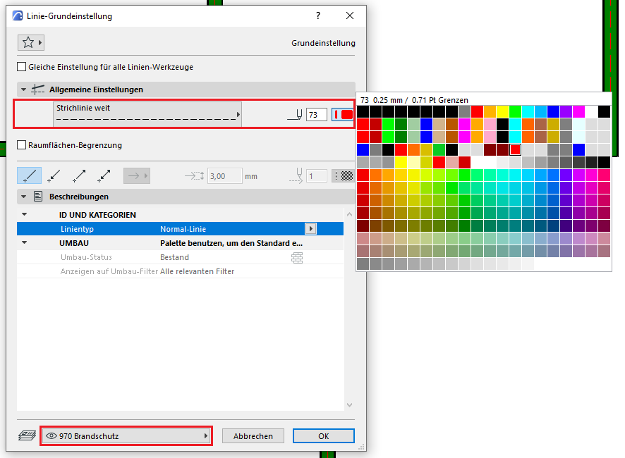
The first step is to enter the fire resistance ratings in the wall settings.
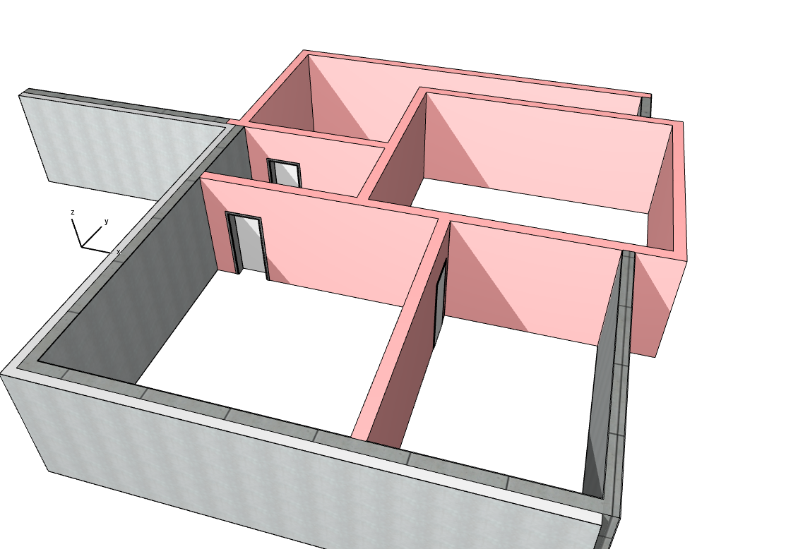
To accurately represent the walls, appropriate graphical overriding rules are required. Below is an example of what such a rule might look like. Once this rule is added to the valid graphical overrides, it can be applied to the fire protection design sections.
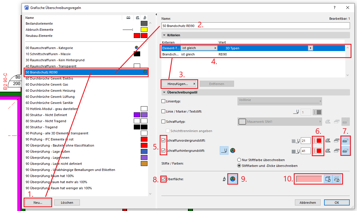
The overwrite displays the affected walls as modified in the floor plan, section, elevation, and 3D views.

Unfortunately, this content is available only to our Pro users.
If you'd like to read the full article, try the Pro account or become a Pro user.